Extra USB Outlet

Time: 4 Hours

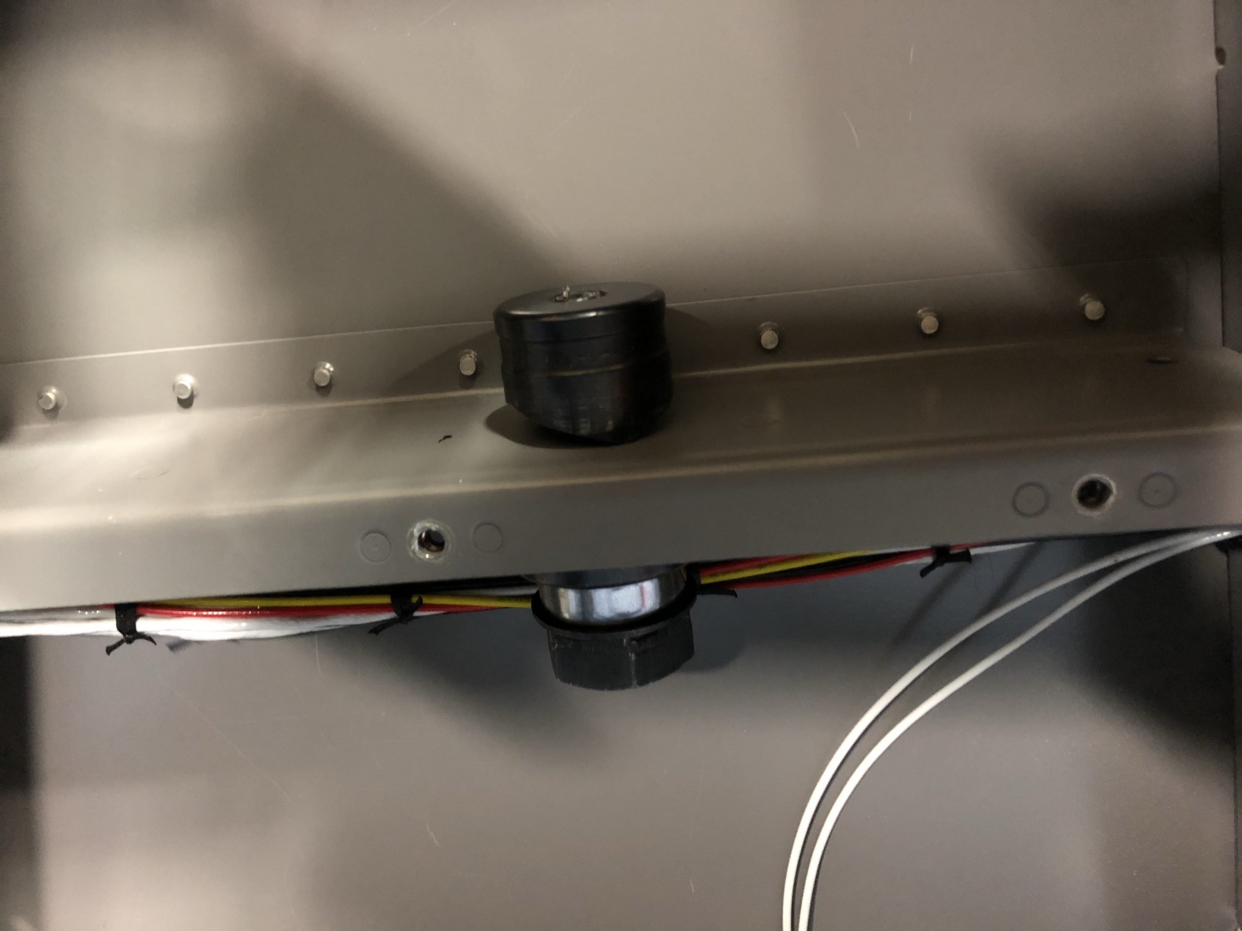
I decided that I wanted to have additional USB ports for charging the iPad and Garmin VIRB camera that I’m going to mount on the roll bar. Since we will usually enter the RV from the left side I will mount the camera on the right side. So the perfect place for the USB’s would be just below the roll bar on the right side. I decided to mount the outlet vertically so the USB’s would be facing up towards the iPad/camera. The horizontal support would work perfectly. I need to conceal the outlet as well as it’s wiring, so fabricating a side wall was the first task to complete. I took some measurements and drew a pattern on some sheet stock I had. I marked for the screw holes and a flange I would bend in the bottom to give the panel strength.
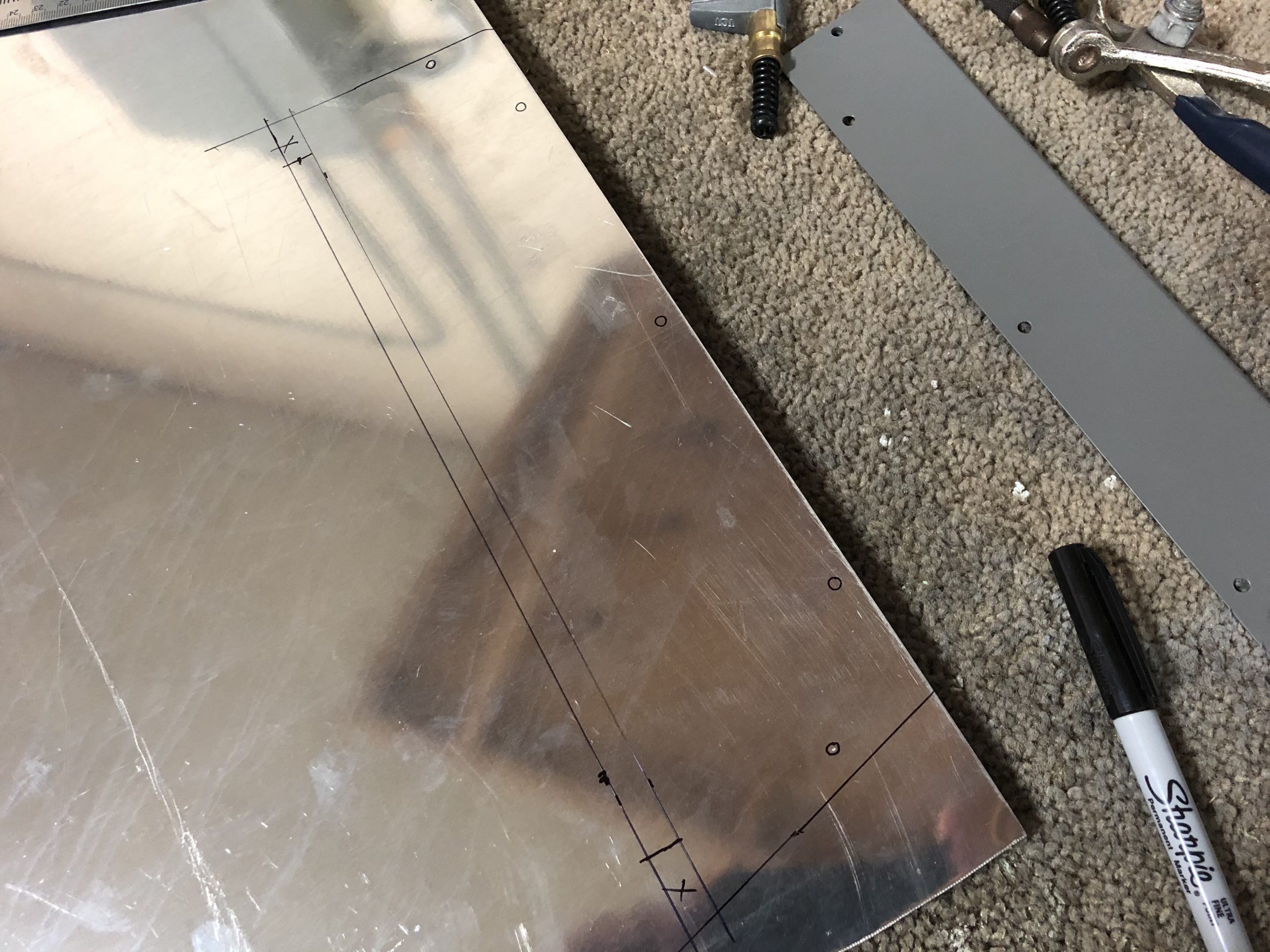
I cut the piece out on did the final shaping and smoothing with the files and 3M wheel. I then used the brake to bend the flange for rigidity. With all the screw holes drills and deburred I put it in place for a trial fit…perfect fit.
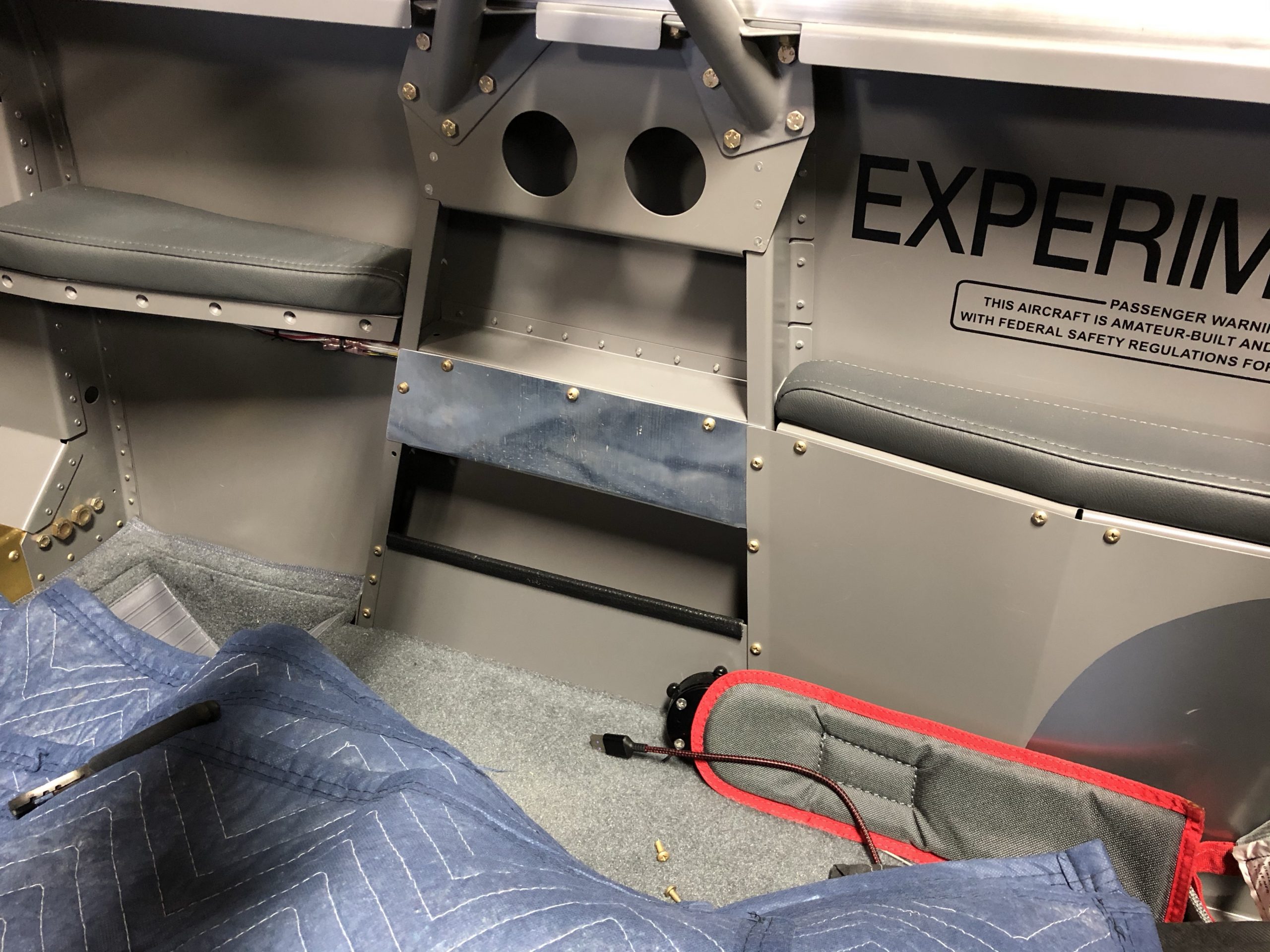
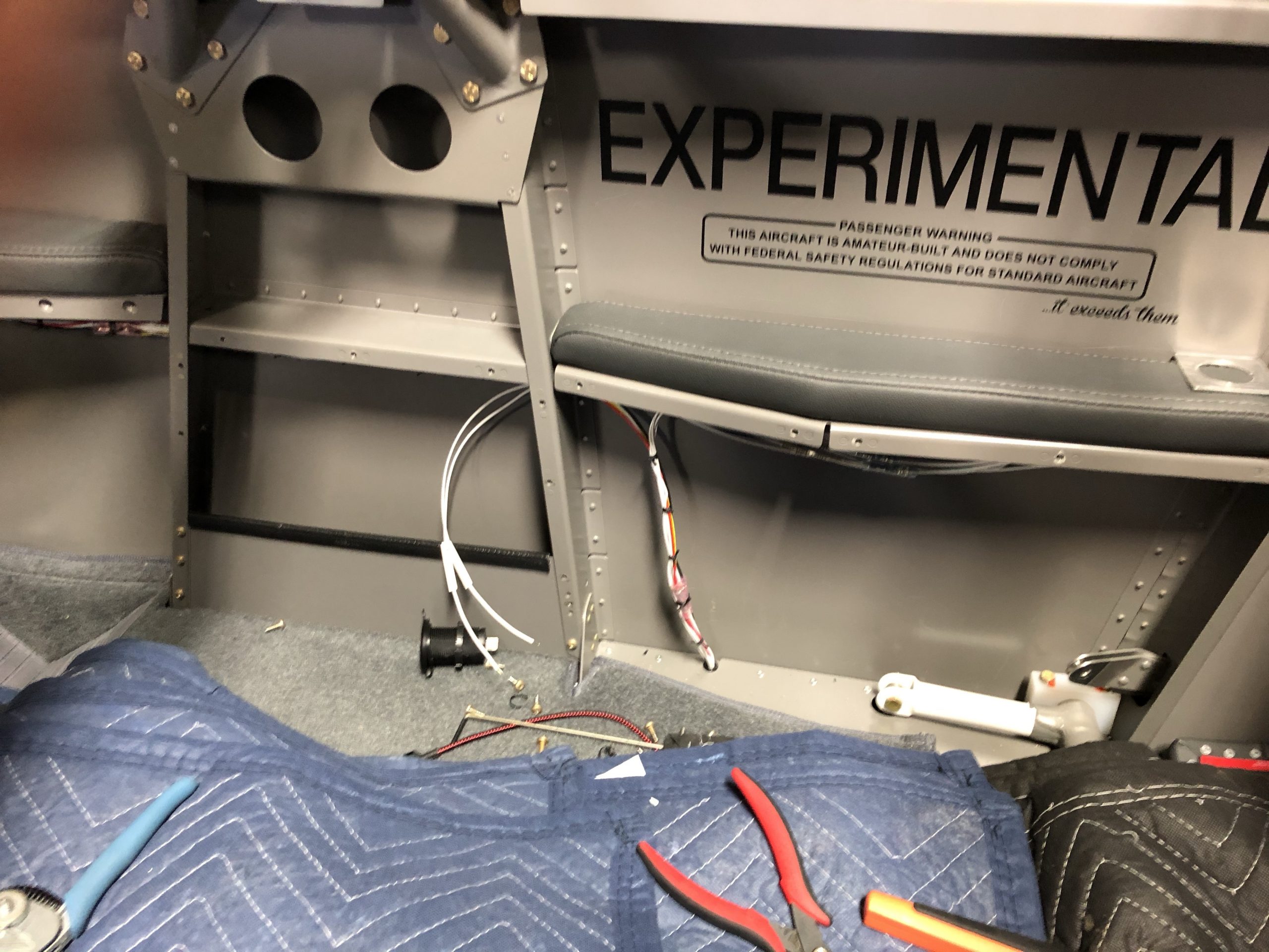
I original put the 12v outlet that was in the bulkhead just behind the passengers right elbow on one circuit that would allow for up to 10 amps. For the USB outlet that I’m going to replace there the total amps would be 4.8. So I could tap into that power source to provide for that new outlet. I removed the passenger right side panel to expose the wire bundle and located the two wires, ground and power, for the aft outlet, I will call the new outlet then mid outlet. I cut the two wires and labeled them with my shrink tube label machine. I crimped a butt splice onto the wires that lead to the aft outlet. The other ends of the wires I put into the splice but also added another 18awg wire to each for the new mid outlet and labeled them as such. I ran those new wires through the bulkhead and into the space just under where the new outlet will be. I re-laced all the wires back together and cleaned the harness back up.
Now that the wires were all crimped and run to the new location I could work on putting the outlet into the support arm. There are a couple of rivets that I used to plug some homes and the nutplates in the flange(I put those in a long time ago for side panel that I didn’t use) all of which I needed to work around when deciding the spot for the outlet. Once I determined the spot I drilled a #30 hole followed by 3/8” hole using my step drill bit. Then I used my 1-1/8” hike punch to create the final hole.
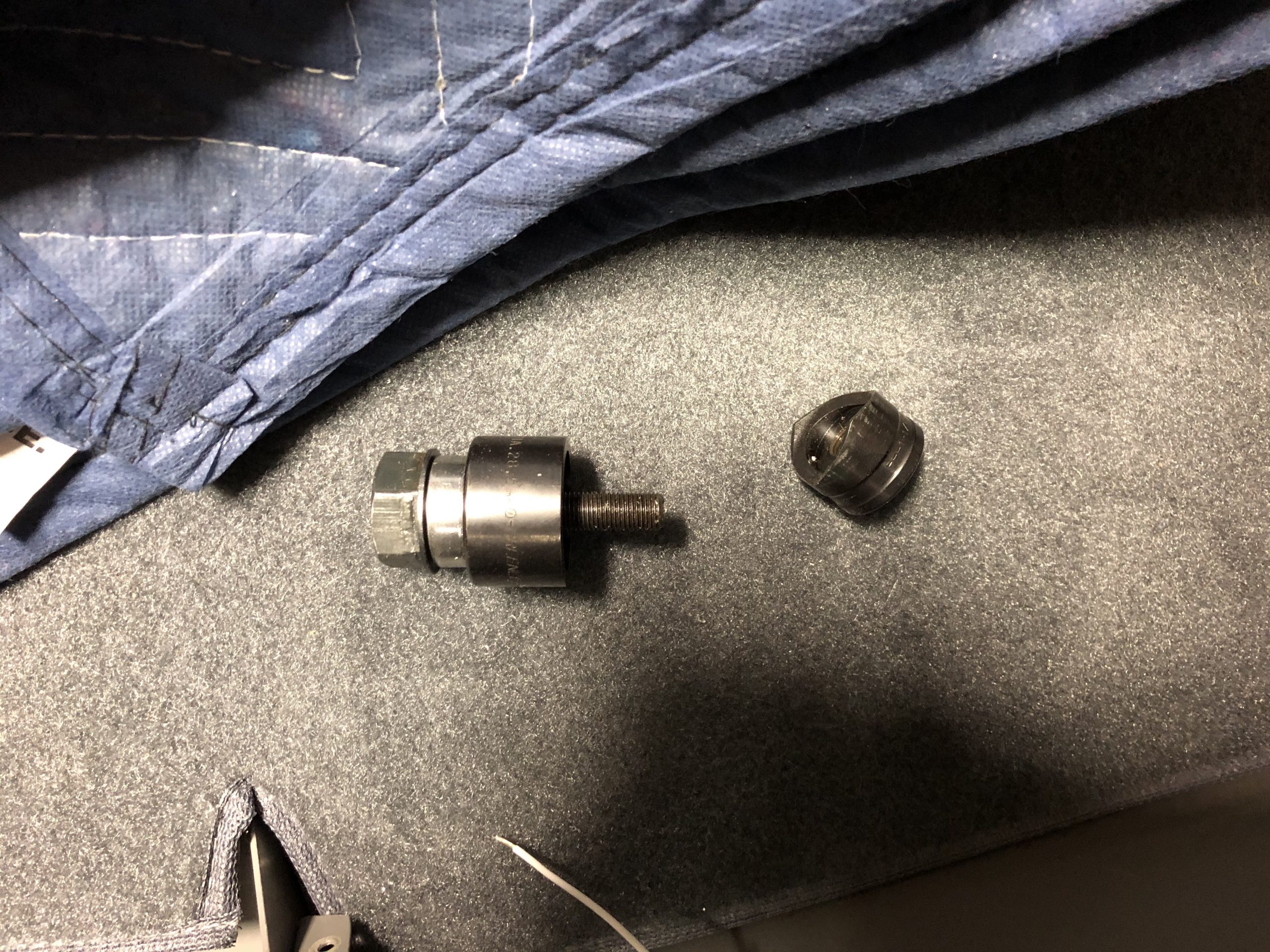
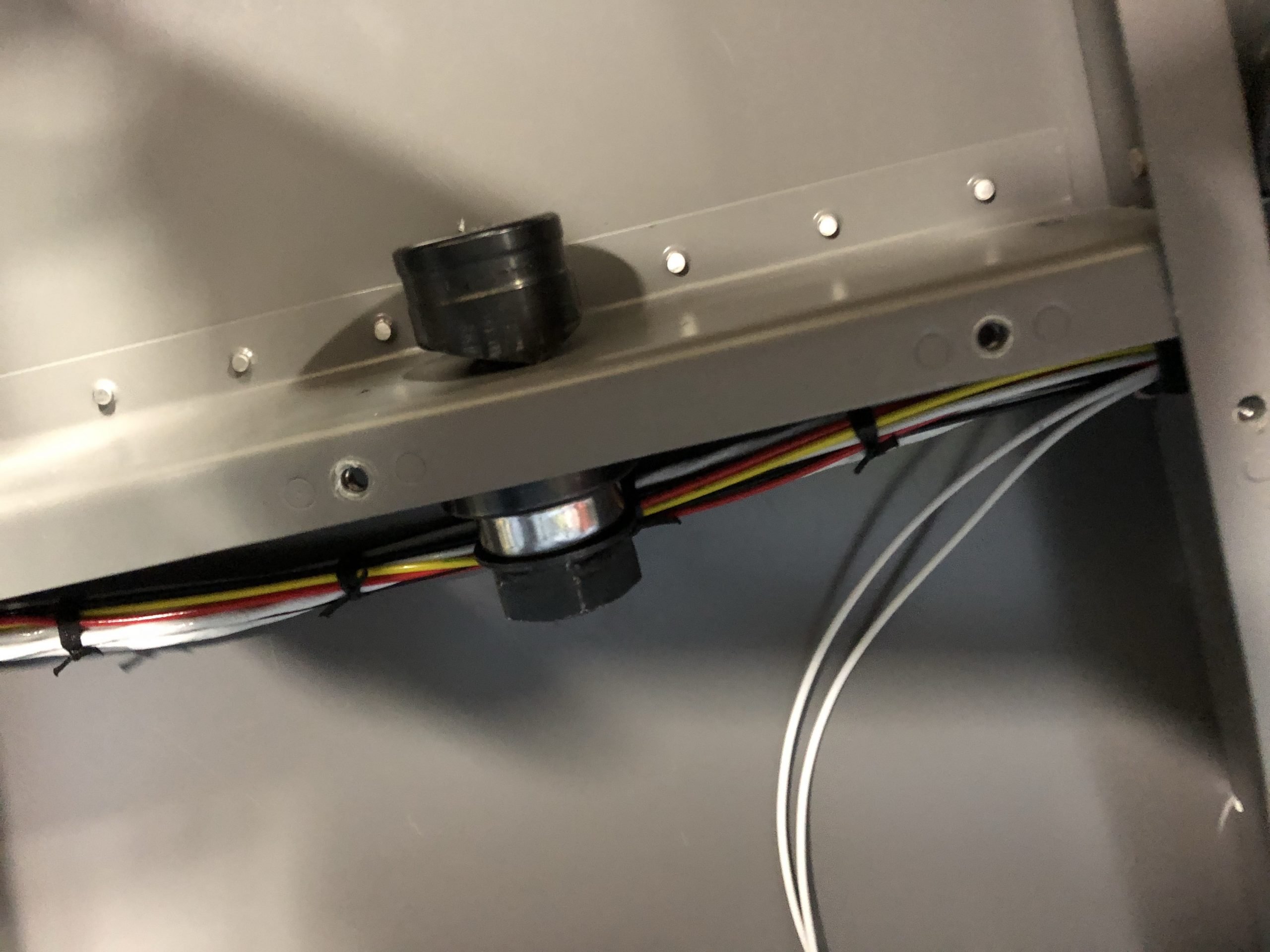
The punch makes a perfect and clean hole that only requires a little edge cleaning compared to drilling. I then put the outlet in place and secured the nut to hold it tight. I labeled and crimped on the 1/4” tabs to attach the wires to the outlet. Once connected I pushed the extra wire back into the side panel area and laced them up.
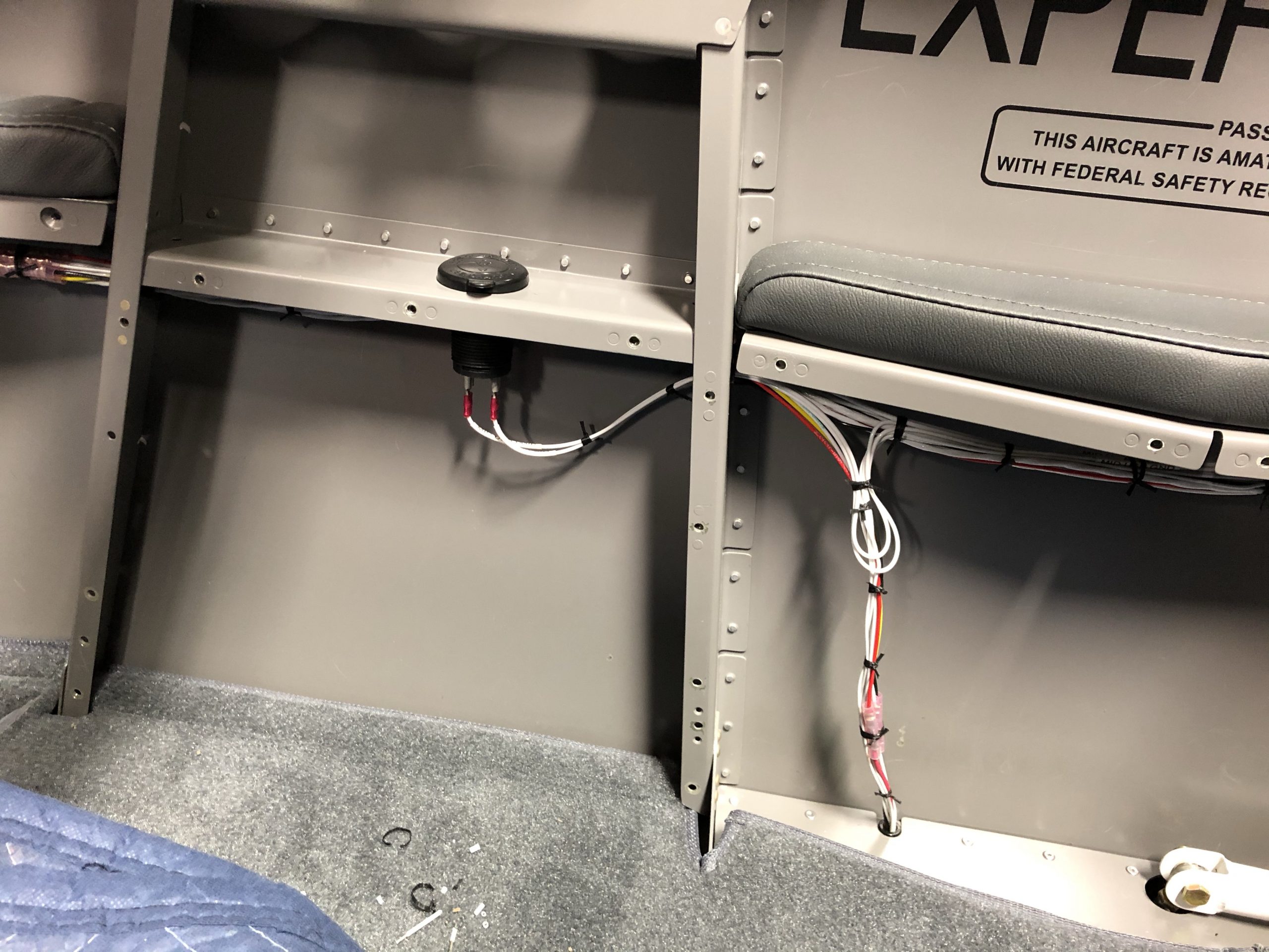
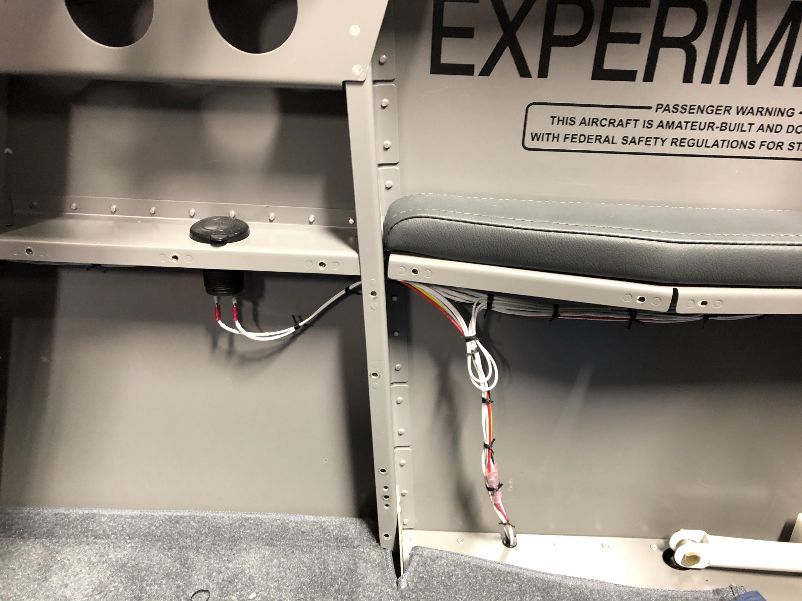
A quick power up of the RV’s electrical system and the outlet worked perfectly. I spent the next hour cleaning up all the tools and replacing the side seatbelt and panel back in place. I primed and painted two coats on the new side panel and will install it when it’s dry and durable. So now I will have two USB ports by the instrument panel on the right armrest, two at the passengers right elbow and three(two in the outlet and the original single one in the bulkhead) for the mid area. We should have plenty of charging capabilities and able to keep everything powered up without cables all over.

Dynon SkyView 7”

Time: 1 Hour

My second SkyView screen arrived from Dynon directly. The process to install was simple as I had all the wiring harnesses done a couple years ago. So I just needed to plug in the three cables and screw it into the panel. I powered it up and went through all the steps to get it synced with the other screen as well as all the other devices.

I’m not sure how I will set up the screens and their layouts. I want to fly a little see what I like best. That’s the nice thing about Dynon SkyView is that you can setup and customize the screens to your liking. Here is a setup that I started with…the PFD(Primary Flight Display) at 80% on the 10” screen, the EMS(Engine Monitoring System) at 20% on the 10” screen and the Map screen at 100% on the 7” screen. Now all that’s left is the Garmin GTN 625xi GPS and my avionics are done.

Transponder & ADS-B

Time: 4 Hours

I installed the transponder and ADS-B units today that arrived from Aircraft Spruce. I had done most of the legwork for this install several years ago by installing the Dynon cables as well as the antennas. I had also created a shelf that I installed both COM radios that would also hold the transponder and the ADS-B units. For those of you that are reading this and unfamiliar, the transponder is the unit that sends a discreet signal to air traffic control for their radar identification. The ADS-B Is a fairly new required system that provides much more detail to air traffic control about where your aircraft is, its movement and information. It also has the ability to receive more information, such as weather radar and airport weather reports.

To start this project I need to remove the shelf which sits just behind the aft baggage compartment.Before I did that I crawled back and laid out where the transponder and ADS-B would go so that the wires and antenna cable’s would not interfere with items like the rudder cables or elevator push/pull tube.

With those spots marked I could remove the shelf and take it to the workbench to install nutplates to hold both units down.I decided long ago to use net plates for all of these so that would make it easy to remove with just a screwdriver for future repairs and maintenance.

A test fit looks great!

I then returned the shelf back to its position and bolted it down with the 4 AN-3 bolts. I connected the Dynon working harnesses to each of the four units. I connected the COM antennae cables to the units. Now that the shop was in place and all the units were secured I could measure for the antenna cables for the transponder and ADS-B units. These require RG-400 coax cable like the COM radios. SteinAir.com has helpful videos online including how to crimp BNC & TNC type connectors you RG-400 coax cable. I did a review since it’s been some time since I did the COM cables. It’s not hard especially if you have the correct crimper. I made the transponder cable the correct length and only had to add a TNC end on the transponder side as I had the antennae side done when I installed the antennae.

I planned on doing the ADS-B cable from the remaining length cut from the transponder cable which means I would need two BNC connectors. One for each end…I only had one remaining in my stock. So I could finish that cable and will get to it next week when it arrives from Aircraft Spruce. Here is what the shelf with the units in place looks like in the tail. I just need to add the antennae cable next week.

I could still finish up the computer side of the install without that cable installed. Dynon makes it pretty simple with step by step instructions. I did have to go back into my notes to remember which serial pins I used for each of the units as you need to tell the SkyView system what’s connected to what. Once that’s done there are just a few settings you need to add like your tail number, aircraft dimensions etc. Once that’s done it was time to test everything and see how it looked on screen. I won’t be able to check the ADS-B until I get the cable installed and I may not get a signal on the ground even with that. So inflight testing will be required then. Here are a few screen grabs of the Dynon. You can see several cool things like the pink “cross hairs” that’s my flight director that having two autopilot Serbia allows for. You can also see the green transponder code of 1200 at the very top of the screen in the first screen grab. The second screen grab the transponder is in the standby mode and the autopilot is engaged, the flight director bars get balls added to the end of the flight director bars to indicate that the autopilot is engaged.

I love build days like this and you get to see some cool stuff come to life. I can’t wait to use all this cool tech in the air!

Battery Charging Port

Time: 2 Hours

When I decided to put the battery in the lower forward baggage area I also included a cover to make the entire upper area usable for storage. I’m having Abby at FlightLine Interiors make me a carpet piece, that matches the kit I already bought from them, to go over that cover so the entire space is carpeted. With the cover in place and the need to charge the battery I have to remove the cover and connect the clamps to the battery. Not a big deal but since I have time on my hands due to the COVID-19 pandemic my flight schedule is nil to say the least here at United Airlines. So many builders connect wires from the positive and negative posts on the battery and run them through the firewall up to the area where the oil door is on the engine cowl. That way they only have to open the oil door and use a plug, like a two pole SAE plug, to connect a battery charger. For me that doesn’t work great as I have a hidden oil door pin that’s accessed from inside the baggage compartment. So I would have to open the baggage door then open the oil door to charge. So I decided to put the access in the baggage area. I looked around and found one builder used a flush mount SAE port. I like the looks and ordered one off Amazon. There are many brands with different wire sizes. I decided on one and went with 10AWG wire size as my charger has 10AWG wire and wanted to match it just to be safe.

My plan was to install the port on the forward facing side of the aft baggage wall. That way the wires could go straight down into the battery area. Then when I wanted to charge the battery all I would need to do is plug in either the big charger or my smaller trickle charger as needed. I will buy a Odeyssey approved trickle charger for long term use if needed. I don’t plan on letting the RV sit long enough to let the battery get low but you never know.

I wanted to make attaching the port a one man job and since it had four screw holes I fabricated a backing plate that would have four nutplates. This way I could insert the port and slip the backing plate over the wires. I could reach through the avionics door and hold the plate in place while starting one screw. Then the other three would be lined up and installed pretty easily.

Then it was just the process of extending the two wires and installing the port. I then ran the wires down through a bushing into the battery compartment. Then I routed each wire to the posts, in this case I ran them to the hot side of the battery contractor and the ground lug on the grounding tab block. This way the wires are out of the way for battery removal and replacement. Once I had the wires routed I cleaned them up and laced them to the wire runs to secure them.

The battery cover in place. This is where the new carpet piece will go.
Temp plug to see the fit.

Project Update

Time: 8 Hours

So It has been a pretty busy summer for us…mainly for me flying and picking up extra hours so we can save for the propellor/spinner. I have done a lot on the RV that is worthy of posting on the blog. I have been cleaning up little items that were on my to-do list and checking them off. One item that I had added on the list a while ago was to remove all the zip ties I used and replace them with cable lacing. I wish I had just started off learning to lace and going that route from the beginning but I fell into the zip tie trance and how easy they are to put on. One problem with the ties is that they can chafe the wires as well as leave a sharp edge on the tail you cut off. So I watched a few videos and taught myself to lace properly and began to carefully remove the zip ties and replace with lace. I started on the firewall forward area including the engine. I then moved to the harder areas like the battery compartment and avionics bay behind the panel. It was a slow process but very rewarding to make it look professional. Here is just a couple of shots of how it looks with lacing.