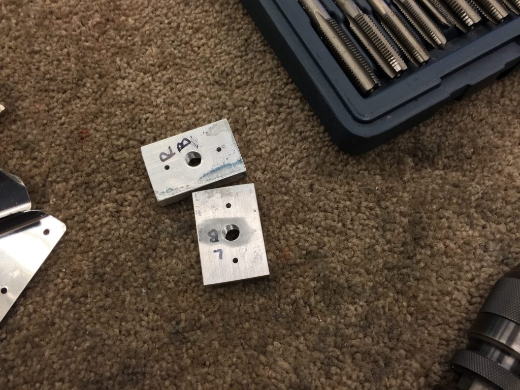
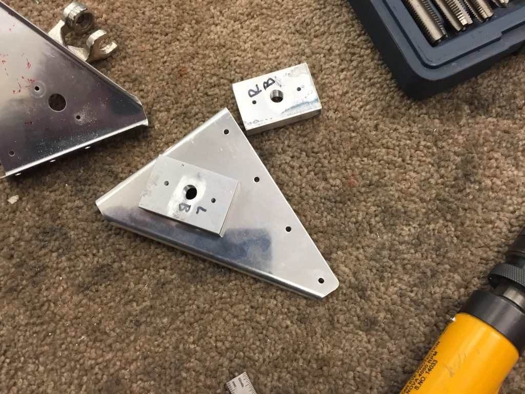
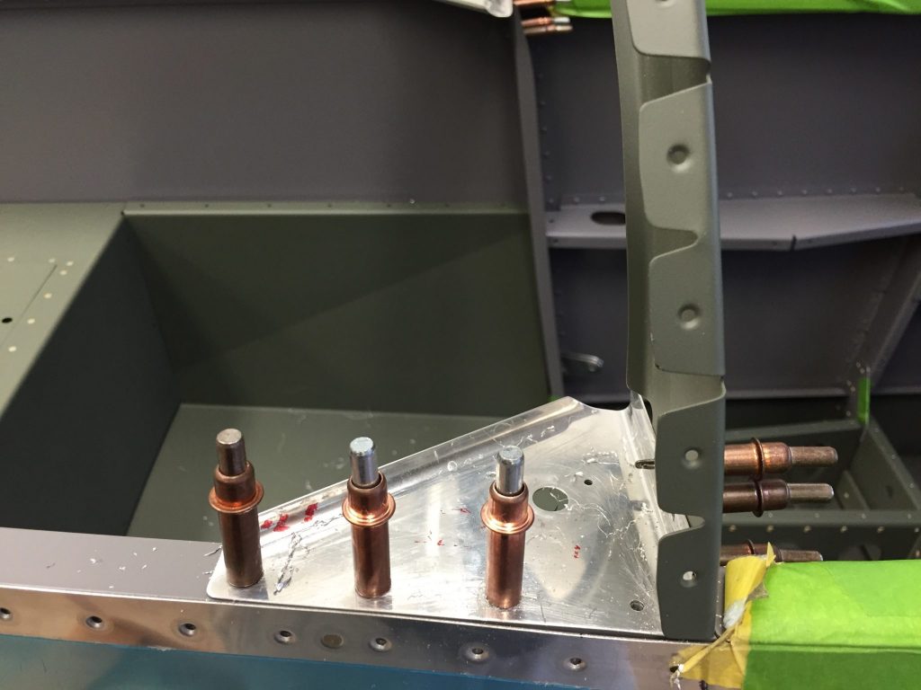
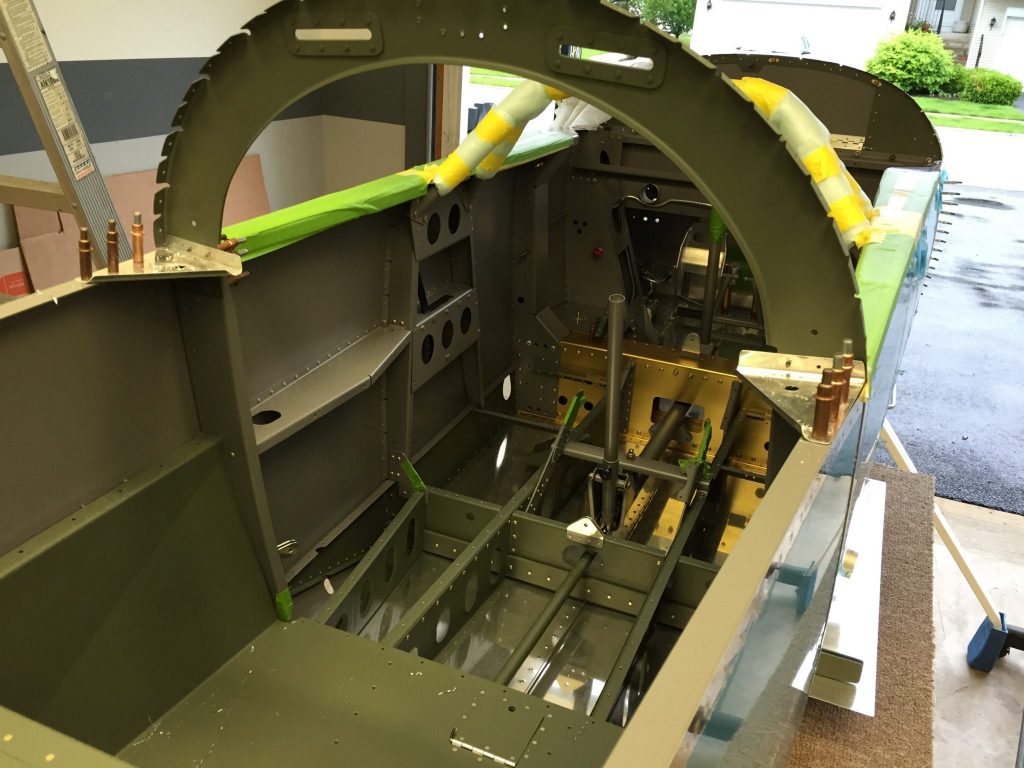
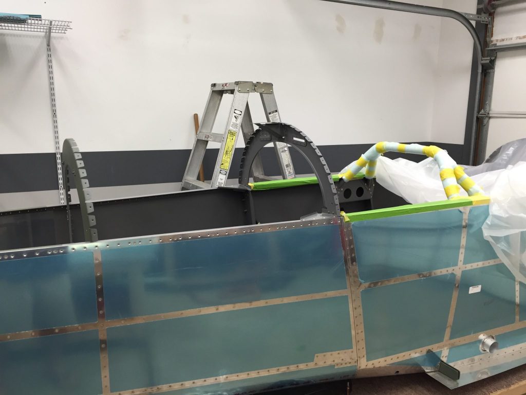
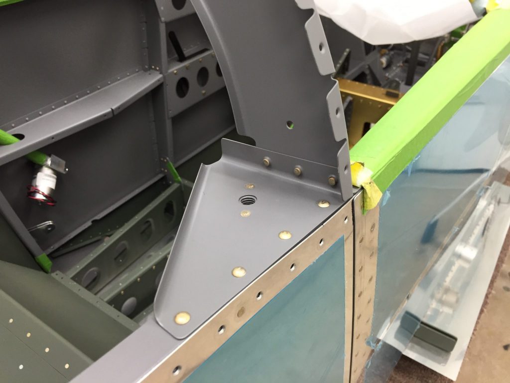
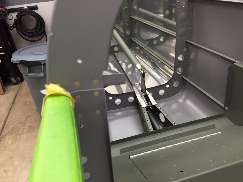
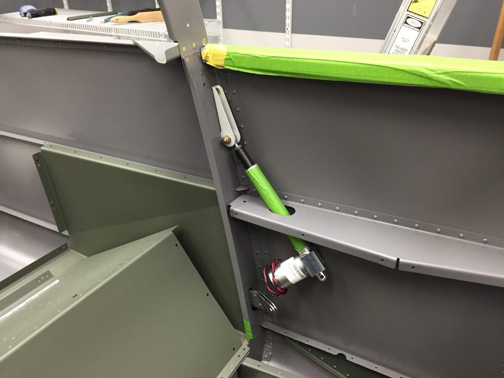
I had a couple hours in the shop before needing to head to Midway airport to pick up my girl :-). I’m still working on items that need to be done before riveting the top skin of the tail. One item is the smoke tank in the aft baggage area. The floor of the baggage area will be permanently riveted in place so I will need to put nut plates under the floor to attach the tank. I made some measurements to see where the best place was for it.
I then measured for four holes and drilled them to a #30 size hole to start with. Then I match drilled it through the floor.
Once I had the holes match drilled I worked on stiffening up the floor to support the tank weight. I used some .032 sheet to make some doublers.
I then figured out where the high pressure line would exit the floor and drilled a 1 1/8″ hole and put a grommet in. With the floor in place I test fit the tank and connections. I cleaned up the doublers and primed them for riveting. I used the back rivet set to get all the rivets and nutplates.
Next up was to work on two of the antanaes that are located under the airplane. One is in the tail area that I need to do before riveting the top skin the other is more forward but identical so I wanted to work on both. These will be for the transponder and the ADS-B radios.
I used the antanae to mark holes on some scrap .032 sheet that would become a doubler. I marked the center of the three holes and drilled a #30 hole in each to use as a match drill to the skin. I then placed the doublers in place to drill down through the doubler and skin. With those holes I used the step drill bit to open the holes to the final sizes. I then cleaned up the doublers and primed them. When the primer was done I put the antanaes in place and tightened them down with the torque wrench.
In between the primer coats I put the panel eyeball lights in place. These are red LED’s that will be on a dimmer and shine across to the side panels for night flying. That’s where I called it a day to head and pickup my girl.
This weekend I wanted to finish up the support brackets for both the ELT and transponder. Before I got to those I riveted the parts of the COM shelf together pretty quickly with the pneumatic squeezer and put it into its place. Some of you might notice that the aft end, side with the notch, have an unusual rivet pattern. I did my best to lay out the rivets so as to not interfere with the attach hardware of the avionics that will be housed there. We will see how my planning is when I get to that stage!
For the ELT and transponder I decided to do side mounts, one on each side. I started with the ELT bracket and made some marks using the actual ELT to make sure there was clearance for the antenna wire and others cables. With the location figured out I used some angle brackets to create a top and bottom bracket and two side supports. I spaced the side supports perfectly for the screw holes in the ELT bracket that comes with it. With everything lined up and marked I removed the bracket and drilled for holes, one in each corner for screws. With the four screw holes drilled I return the bracket to the sidewall and drilled rivet holes in the top and bottom bracket. The top and bottom bracket will be riveted permanently and the two side brackets will be removable with the screws. With everything aligned I remove the bracket again to match drill the ELT’ssupport to the bracket. This support has two clamps that will hold it in place.
My son Chandler came to the shop and helped drill and countersink the holes for the nutplates on the top and bottom brackets. I took all the parts apart and cleaned and primed them. it’s a common practice in the RV-8 to put the ELT antenna laying horizontally in the tail area. This area is covered up by fiberglass fairing and conceals antenna. So I drilled a 3/4″ hole with my step bit and put a grommet in it for the antenna to slide through. The aft and of the antenna will be secured with a adele clamp on the horizontal stabilizer after it is installed.
I screwed in the ELT’s control head in the instrument panel as well. There’s a short cable that connects to a battery powered alert speaker that connects to the control head. There will be a cable run from that alert speaker back to the ELT itself. While I was upfront I went ahead and put in the grommet edging that I had receivedAircraft Spruce in the upper gear towers lightening holes where wires will pass through.
I used some on the pass through for the ELT’s antennas cable. After the parts were dry from priming I riveted the nutplates to the top and bottom supports. I marked out 4 holes on the top bracket and 3 on the bottom to drill for the blind rivets I would use to attach them to the mid and lower longeron.
I used the holes in the supports to match drill the longeron’s with my angle drill. With all the holes drilled and deburred I attached the ELT cradle to the two side supports.
There was a little play with the holes in the cradle so I left them a little loose and place these parts on the side wall with their screws. I tightened them down and then tightened up the cradle screws. With the parts all secure now I grabbed the ELT and put it in the cradle.
I connected the cable that runs from the ELT to the panel mounted control through the flexible conduit I have installed. I also hooked up the antenna wire and secured it with a couple adel clamps and a zip tie anchor.
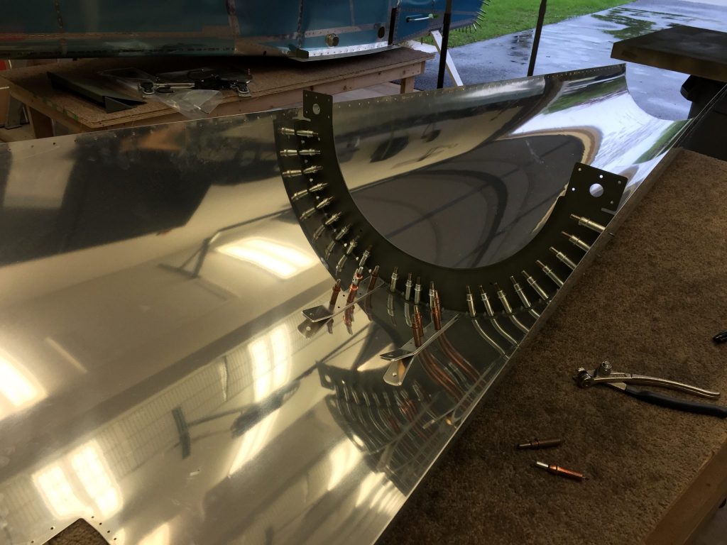
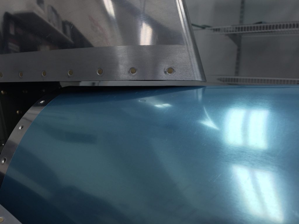
I still have one more bracket left for the transponder but decided to take a break from building these. I decided to work on the rudder cable fairings. I bought these fairings from Avery tools as they look a lot better than the ones you have to fabricate from scratch. I made some marks on the side of the fuselage and came up with a design I liked for the final cut. after a few minutes at the bandsaw and deburring wheel I had both the left and right side done. I carefully align them and came up with a rivet pattern that wouldn’t interfere with any of the items inside. I match drilled the fairings to the skin and clecko’ed them in place. The area that needs riveting on these fairings is pretty small and you have a potential for slipping off the faring with the rivet gun. So I used some sheet the same thickness, .032, to create a ledge to support the gun and secure them with tape.
The riveting went perfect on both side and I had them done in about an hour.
I decided to get the supports and sheet cut for the transponder bracket and drilled the holes for the nutplates.
I decided to call it a weekend and cleaned up shop. This was a fun weekend in the Hanger. I need to finish up the transponder bracket and do the smoke tank installation and I think I have most of the items wrapped up for the aft fuselage top skin to be riveted on.
Today I started the fabrication of the shelf that will hold my two COM radio units and the ADS-B receiver, which allows me to get traffic and weather information. I’m following Glenn’s lead on the style and placement, just forward of the elevator bell crank under the rear baggage top shelf.
I notched out the aft end to allow for plenty of clearance with the bell crank. The outside edges are 1/8″ wider than the radio units and will allow the attach hardware to have plenty of room. In between the part making I primed the other shelf I already finished.
I ran home for lunch and my grommet edging arrived from Aircraft Spruce, this will line any metal holes that wires go through that is too big for regular grommets. When I got back to the hangar I cleaned up the parts of the COM shelf and countersunk the holes on the sheet for flush rivets. Once all the parts where some I started priming them. In between coats of primer I riveted the ADHARS shelf together and put it in its place.
When the primer for the COM supports was dry I riveted the aft pieces together. I had to make the support out of three parts to allow for the cut out where the bell crank is.
While I was waiting for the sheet to dry I drilled all the nutplate holes for the COM shelf. I had to countersink the holes using my angle drill since there isn’t much room there. The pneumatic squeezer made quick work of the riveting.
While I was working on the nutplates I noticed that I forgot to install the second flexible conduit on the right side of the fuselage. This side required a new hole to be drilled in the middle floor rib as there wasn’t one there like the left side. I used my step bit and had that done pretty quick. I ran the conduit and secured it with zip ties.
Another task I got done was to run the static air lines to the ports I had Pro-Sealed the other day. I ran from one port to a tee then to the other port. From the tee I went through a adele clamp and to a 90° elbow. Later I will run a line from that elbow to the two ADAHRS units.
As you can see in a couple of the last photos I have some paper templates of the ADAHRS units. I used the actual dimensions from the Dynon Skyview manual and plugged them into my vinyl cutting software. I then printed the outline and text using that software to my printer. The software also adds three registration marks that when I take the printed card stock and put it into my vinyl cutter it scans those marks and knows the exact layout. It then makes precision cuts along the edge and gives me an exact size template of the units. I used them to help build and align the rivet pattern for the avionics units. That’s where I stopped for the day. Tomorrow I will finish up the COM shelf and work on the ELT and Transponder mounting brackets.
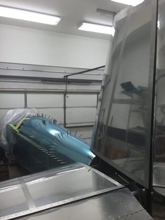
I started the tasks that I need to get finished up before I can or want to start riveting the aft top skin, turtle deck, on. The first thing up was to drill all the required holes for snap bushings for wire runs. I have two runs that head to the back, pitch trim and tail light.
In the 1″ holes in the gear towers I used rubber grommets I got from McMaster Carr this week. Once all the holes were drilled and either a grommet or snap bushing was in place I started routing the wires. First up was the tail light and its 3 conductor shielded wire. I started in the tail and ran my way forward going through the snap bushings as well as some well placed adele clamps along the way.
After I had the wire run up behind the panel I used some 1″x 1″ adhesive backed zip tie anchors from Home Depot to add some anchor points.
I also ran some flexible conduit along the left and right side along the bottom ribs so that after the floor gets riveted in place I can run wires later if needed.
With the conduit run and secured with zip ties I ran the pitch trim wire from the tail to the pack of the panel. I used 5 conductor shielded wire the SteinAir recommended.
I ran the remainder of that wire from the panel to the aileron trim servo tray as well. I then moved to the static port installation in the afte side skins. For the non-aviation readers these ports give a “static” air reading to compare to ram air as the aircraft is moving for airspeed or a sealed pressure in an altimeter to measure altitude. I’m using the SafeAir pitot-static line system. I came up with the locations on both sides and drilled the holes to 1/4″ with a step drill bit.
I placed one of the ports in place to check the clearance on the bulkhead rib. The next process is to secure the ports to the side skins. You can rivet these but I decided to just use ProSeal to secure them as many other builders have done. So I broke out the ProSeal stuff and mixed some up and sealed the ports to the skins. I cut a piece of wood to act as a brace to hold them until they cute.
Next up was to tackle the 2 shelves that I want to house the avionics. The first one I started on was for the to ADAHRS units that will supply the instrument screens with the attitude references it needs. I started with some 3/4″ x 3/4″ angle to make two supports across the upper longeron. This is a perfect place as they are level with the longitudinal axis and that’s what the ADAHRS need.
I added some .032 sheet to the cross supports to make a shelf for the units to sit on.
I also made a bracket out of some angle to bolt a Tee for the static line to. After the static ports cure I will run the lines to them and to the new shelf I built for later installation. Fun day in the Hangar!
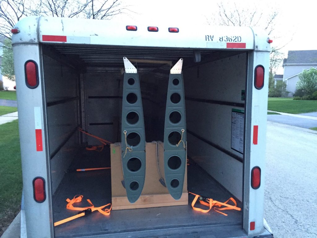
I didn’t spend 10 total hours on just the aft bulkheads. This post is a cumulation of several days of building. My girl, T, and I bought a new home and I recently sold my townhome in one day. So that means between flying, building and other stuff I have to pack and orginize all my house stuff. We close on my home at the end of May which is why I’m getting a jump start on stuff. In between boxing and wrapping I get a little RV work done in the Hangar. First up was the big move of the wings to my buddy Glen’s for storage until the house move. We had a UHaul trailer that I moved some left over stuff from Omaha. While I had the trailer we took advantage of it and loaded the wings.
The next day I received my smoke kit from Smoking Airplanes and inventoried it. I had bought a few camlock connectors, from Agrimart, that I wanted to see if I could use them to make removal of the tank easier. From the initial setup I think I will be able to make these work.
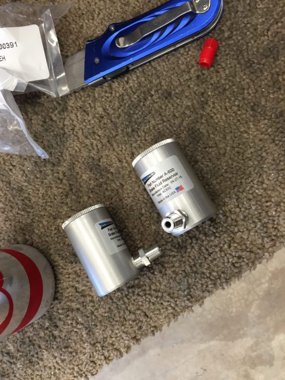
Along with the different connections I also had them turn the pump 90° clockwise sonthatbthe output would be facing forward for easier access. Another package that arrived was from Aircraft Spruce that had my brake master reservoir. The plans call for having one master reservoir and running plastic lines to each of the brake master cylinders on the rudder pedals. The ones I ordered are smaller and thread directly into the master cylinder for each of the brakes. This eliminates having the plastic lines and gives a nice clean look.
The only downside I can see with these reservoirs is that it limits the amount of forward movement if you put the rudder pedals in the furthest forward setting. This wouldn’t be a problem for me as I will most likely use the second or third setting which give me plenty of movement. So I grabbed the rudder pedal assembly and installed the master reservoirs. Once I was happy with how they looked I installed the rudder pedal assembly into the forward fuselage.
Moving on the next task was to install the aft upper bulkheads. Before I could do this I needed to take care of two tasks, the passenger shoulder harness connection points and the tiedown ring guesset. The harness attach points are pretty easy as you really just need to clean up the edges and carve out some of the end material to allow them to sit flush with the underside of the aft skin whil overlapping the bulkhead flange.
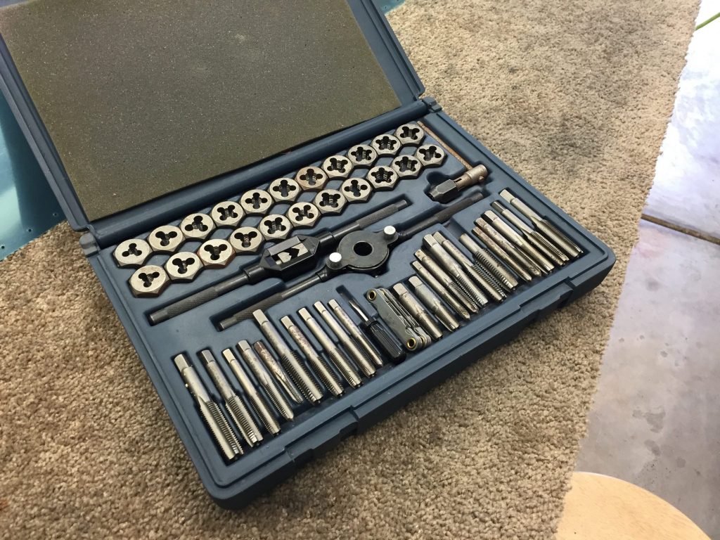
The tie down ring gusset was next. This gusset if structural support behind the passengers backrest bulkhead and the upper longeron. You also have the option of putting in a tie down ring storage in this spot. This is for the Van’s tie down rings that are meant to be removed before flight and stored here. If you can remember I went with smaller aftermarket ones that can stay in all the time. I still went ahead with the plans just in case I ever wanted the bigger rings I would have this done now. I bought som 3/8″ thick bar stock from McMaster Carr and cut and drilled per the dimensions. I then grabbed my tap set and tapped for 3/8″-16 threads needed.
Before riveting those in-place I put them on the bulkhead and matched drilled the longeron’s.
A couple days later I was finished with priming, painting and riveting all these parts.
Next I installed the upper flap moter bracket and installed the flap moter. I didn’t instal the lower end as the floors are not in yet.
From there I wanted to see if I needed to trim the bottom of the VS at the forward end. Some builders, including Glen, had to trim this a little as the skin was in contact with it. I guess I was lucky as mine was just fine. When I called T to come look at the progress she made me get in a shot. 😀
As with this entire build I got to take all the parts off including the VS so I could work the up and down travel of the elevators. There are two travel stops, one for the up and one for the down. These limit the travel of the elevator horns and can be adjusted. The forward movement or down elevator has a limit of between 20°-25°. As mine stood with no change I was at 23°. Due to the horns not being matched only the left one hit the stop when you really want both. After discussing this with my buddy I decided it’s not a big deal as it would be very rare if at all that you would got that stop in flight. So I left it as is and worked on the aft or up stop. This one could be hit inflight especially in acrobatics so I would work at it to get both hitting. The final product was to trim the right side of the stop to almost flush and the left about 1/4″ remaining. I angled both sides so that most of the flange of the horns came in contact. I achieved 26.8° with the range between 25° and 30°. I’m happy with this result.
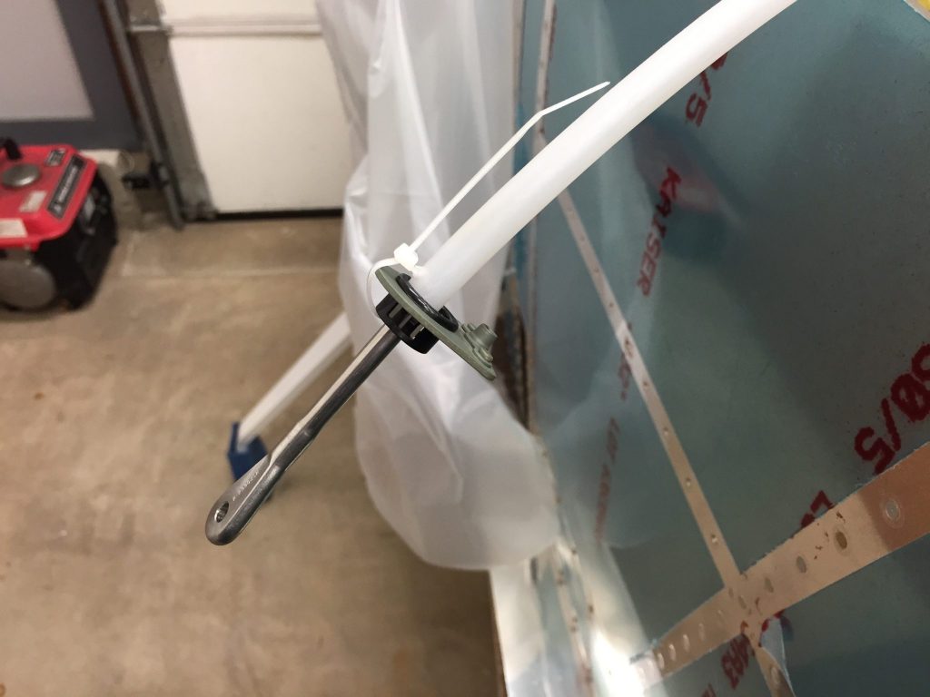
Last night I decided to do a little work which consisted of installing the rudder cables. There are two protective sleeves one for the aft exit hole and one for the section that lies next to the passenger foot wells. You start from the aft end and feed the cable through snap bushings and holes in all the bullheads. Before going through the center section you need to secure the end of the protective sleeve to the floor support snap bushing. You drill a small hole in the sleeve and zip tie it to the bushing and bracket.
After feeding it through all the holes I went back to secure the aft end with an Adell clamp.
Here is a view of the cables running the length of the fuselage.
Some of you may notice an error in the last photo…yep I installed the forward sleeve aft of the secure point! It should be forward of that point and go into the yellow center section there by protecting the cable for the foot well. Not a big deal and I just cut the zip tie’s and slid them forward, put a new hole in that end and re zip tied them.
So that’s my multi day post. These next 5 weeks will be spuradic as I close on my home in 3 weeks and close on our new home in 5 weeks. That means reduced a Hangar time and a couple of weeks of no hangar time when we are homeless! I’ll try my best to keep you updated.
 I then measured for four holes and drilled them to a #30 size hole to start with. Then I match drilled it through the floor.
  Once I had the holes match drilled I worked on stiffening up the floor to support the tank weight. I used some .032 sheet to make some doublers.
 I then figured out where the high pressure line would exit the floor and drilled a 1 1/8″ hole and put a grommet in. With the floor in place I test fit the tank and connections.

 I cleaned up the doublers and primed them for riveting. I used the back rivet set to get all the rivets and nutplates.
 Next up was to work on two of the antanaes that are located under the airplane. One is in the tail area that I need to do before riveting the top skin the other is more forward but identical so I wanted to work on both. These will be for the transponder and the ADS-B radios.
  I used the antanae to mark holes on some scrap .032 sheet that would become a doubler. I marked the center of the three holes and drilled a #30 hole in each to use as a match drill to the skin. I then placed the doublers in place to drill down through the doubler and skin.
 With those holes I used the step drill bit to open the holes to the final sizes. I then cleaned up the doublers and primed them.

 When the primer was done I put the antanaes in place and tightened them down with the torque wrench.


 In between the primer coats I put the panel eyeball lights in place. These are red LED’s that will be on a dimmer and shine across to the side panels for night flying.
 That’s where I called it a day to head and pickup my girl.