Today started with work on the instrument panel parts. Lots of edge deburring on the support structure as it has tons of tabs that allow it to curve.
After all the edge work I clecko’ed the parts together, as you can see the center panel is offset down one hole, this allows the parts to be inserted into the fuselage and still give you access to the clecko’s. This panel will eventually be held into position with screws allowing you to remove it to work on your flight instruments.
I needed to countersink all the holes in the two side panels so that the instrument panel will lay flat.
I then clecko’ed the parts together and put them in their place.
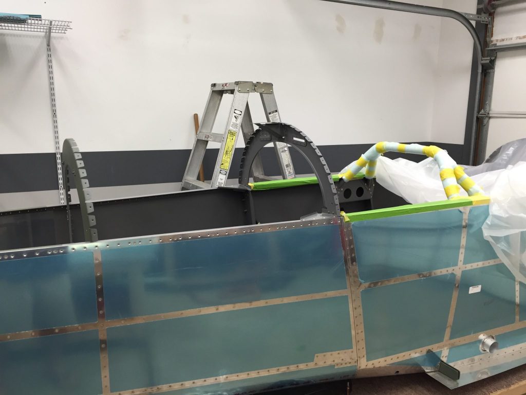
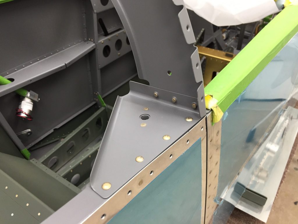
Since I needed to put the windscreen roll bar in next and it’s not painted yet I moved ahead to the forward top skin and started working on those parts. There are two filler strips that make a lip for the forward baggage door to lay on when closed. I cleaned their edges and deburred them.
The top skin has two parts that need to be cut out, the first is the baggage door area and the second is the cut out for the glare shield above the instruments. I used my dremel to cut these out and clean the edges up.
I then cleaned up all the edges on the top skin and then clecko’ed the filler strips to the underside with just a couple of clecko’s. Then the skin got layer on top of the fuselage to start clecko’ing it in place. From this point I decided to clean up shop and grab the stuff I needed to paint the roll bar at home in the garage. I will get it painted tonight and have it ready for the next couple of days. A good day in the hangar!
I spent a whole day just getting orginized in the new shop and figuring out where to place things.
Next I needed to figure where to put the blueprints since I don’t have the counterspace like I used too. What I decided was to use some sort of easel and started to look for ones to buy. What I found I didn’t like so I decided to build a simple one to suit my needs. After making some measurements I headed to Home Depot to get the supplies. I spent a good part of the afternoon cutting and building this thing.
So I was ready to do some riveting. First up was to final drill the remaining holes for the windscreen rollbar where I had left off around 6 months ago.
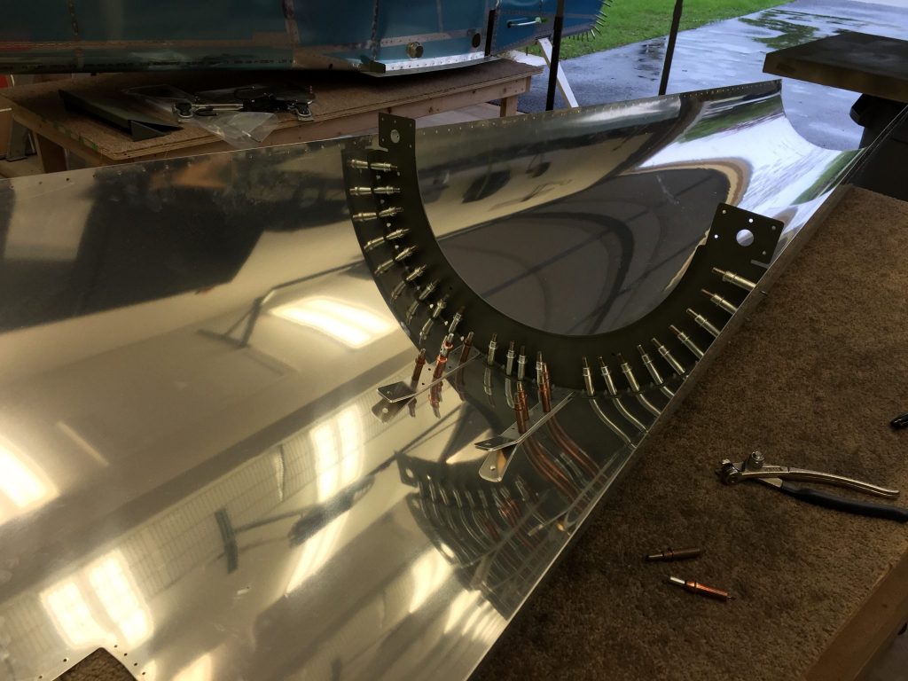
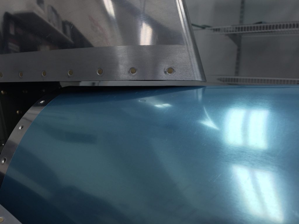
Next up was to rivet the lower and upper forward baggage sides to the gear tower cross brace. Here we go starting off riveting the AN470 rivets which are the toughest in my opinion. I couldn’t use the squeezer so it was gonna be the gun and bucking bar. So i grabbed the tools and took a deep breath. With a gentle squuze of the trigger I set the first rivet perfect followed by the second. Feeling good I headed to the 3rd rivet and let my guard down with the gun. If you dont hold good pressure on the gun it can bounce off the rivet head and damage parts. This is exactly what I did and put 3 dents in the lower baggage side as can see in the photo. Ugh I hate when I do dumb things but this is what happens when you take 6 months off! The good thing is that I will probably cover this area with some type of carpet since it will take a beating with bags and tools for flights. Well I took a 10 minute break to clear my head and sulk in my error. Well they say these things add character to your aircraft, all I can say is my aircraft will have a lot of character! I then riveted the bottom baggage side to the side walls. At least these set perfect and look good! 🙂 I decided to clean up the shop and head out to have date night with my girl. Minor ding that will never be seen by most people and some progress. I feel good about getting back into the swing of building.
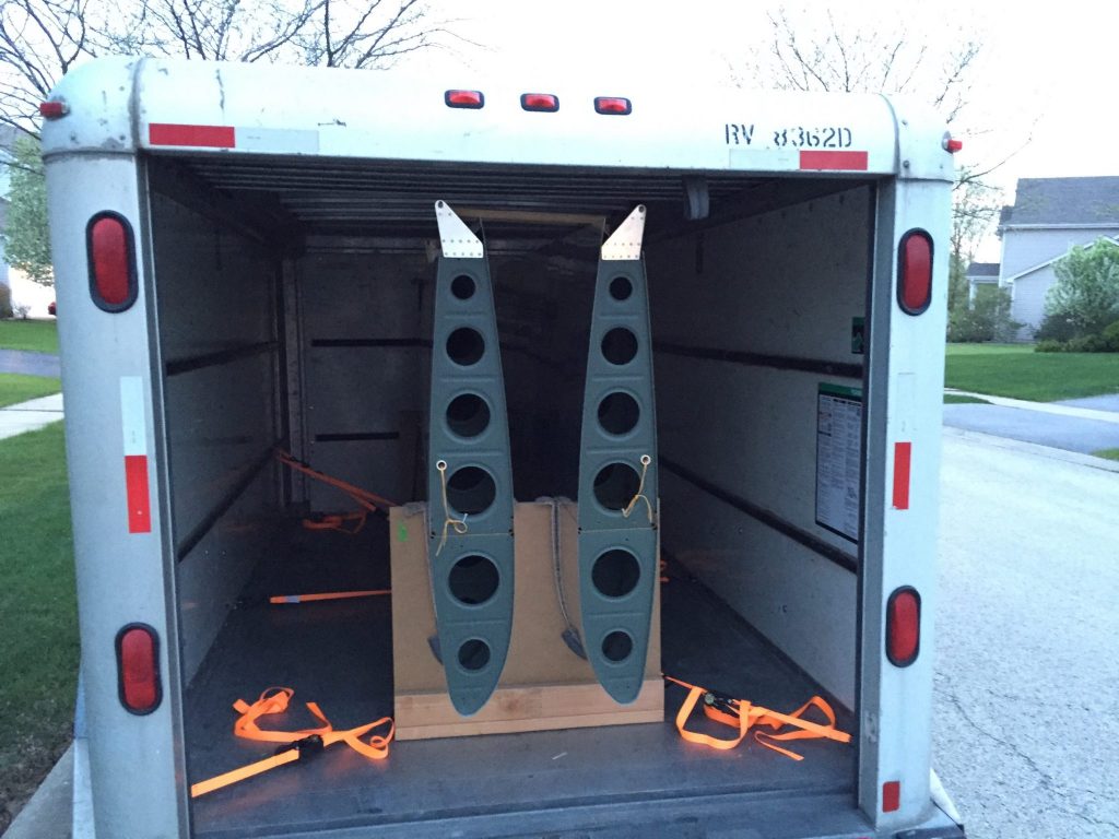
I didn’t spend 10 total hours on just the aft bulkheads. This post is a cumulation of several days of building. My girl, T, and I bought a new home and I recently sold my townhome in one day. So that means between flying, building and other stuff I have to pack and orginize all my house stuff. We close on my home at the end of May which is why I’m getting a jump start on stuff. In between boxing and wrapping I get a little RV work done in the Hangar. First up was the big move of the wings to my buddy Glen’s for storage until the house move. We had a UHaul trailer that I moved some left over stuff from Omaha. While I had the trailer we took advantage of it and loaded the wings.
The next day I received my smoke kit from Smoking Airplanes and inventoried it. I had bought a few camlock connectors, from Agrimart, that I wanted to see if I could use them to make removal of the tank easier. From the initial setup I think I will be able to make these work.
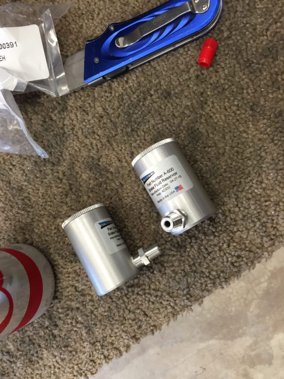
Along with the different connections I also had them turn the pump 90° clockwise sonthatbthe output would be facing forward for easier access. Another package that arrived was from Aircraft Spruce that had my brake master reservoir. The plans call for having one master reservoir and running plastic lines to each of the brake master cylinders on the rudder pedals. The ones I ordered are smaller and thread directly into the master cylinder for each of the brakes. This eliminates having the plastic lines and gives a nice clean look.
The only downside I can see with these reservoirs is that it limits the amount of forward movement if you put the rudder pedals in the furthest forward setting. This wouldn’t be a problem for me as I will most likely use the second or third setting which give me plenty of movement. So I grabbed the rudder pedal assembly and installed the master reservoirs. Once I was happy with how they looked I installed the rudder pedal assembly into the forward fuselage.
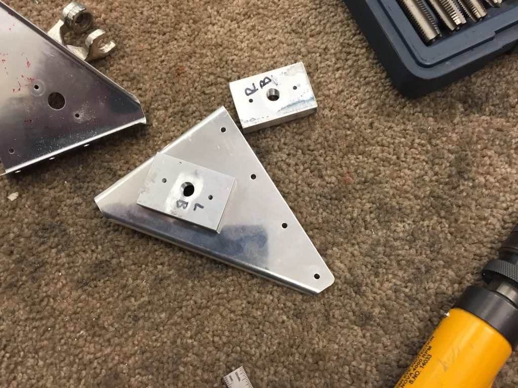
Moving on the next task was to install the aft upper bulkheads. Before I could do this I needed to take care of two tasks, the passenger shoulder harness connection points and the tiedown ring guesset. The harness attach points are pretty easy as you really just need to clean up the edges and carve out some of the end material to allow them to sit flush with the underside of the aft skin whil overlapping the bulkhead flange.
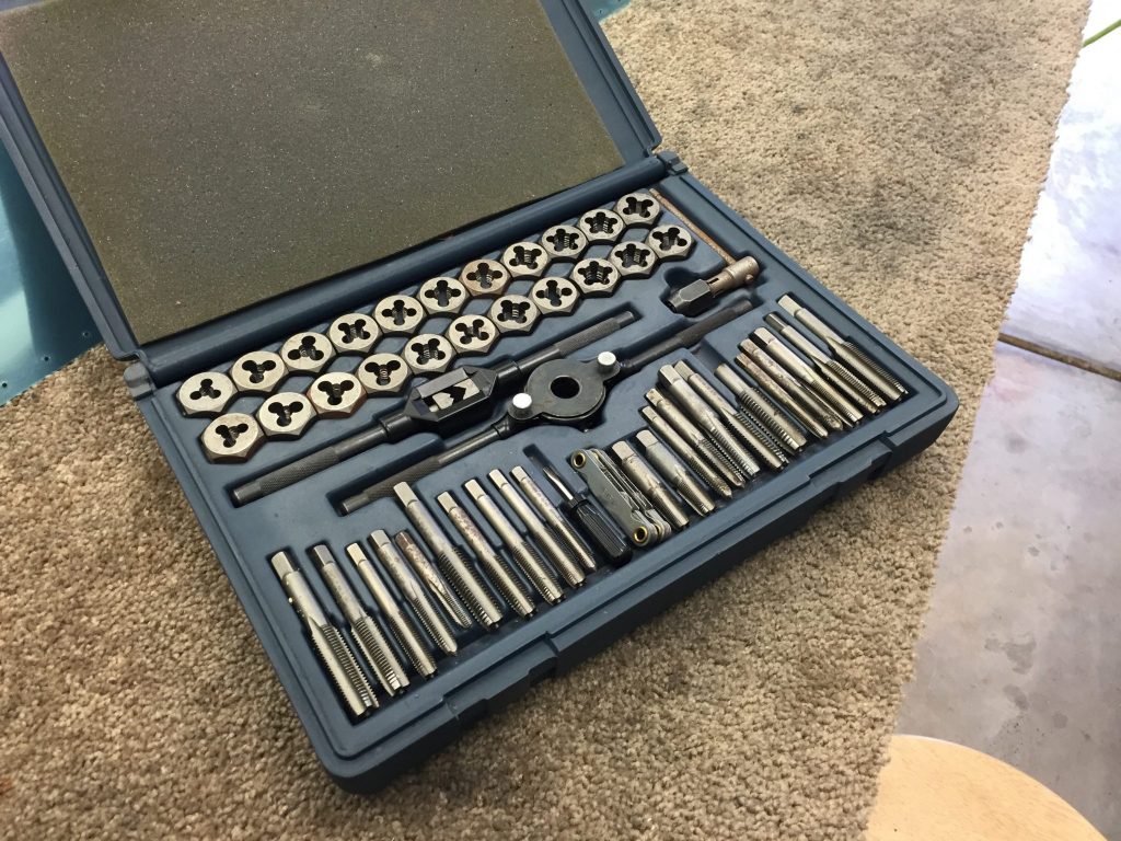
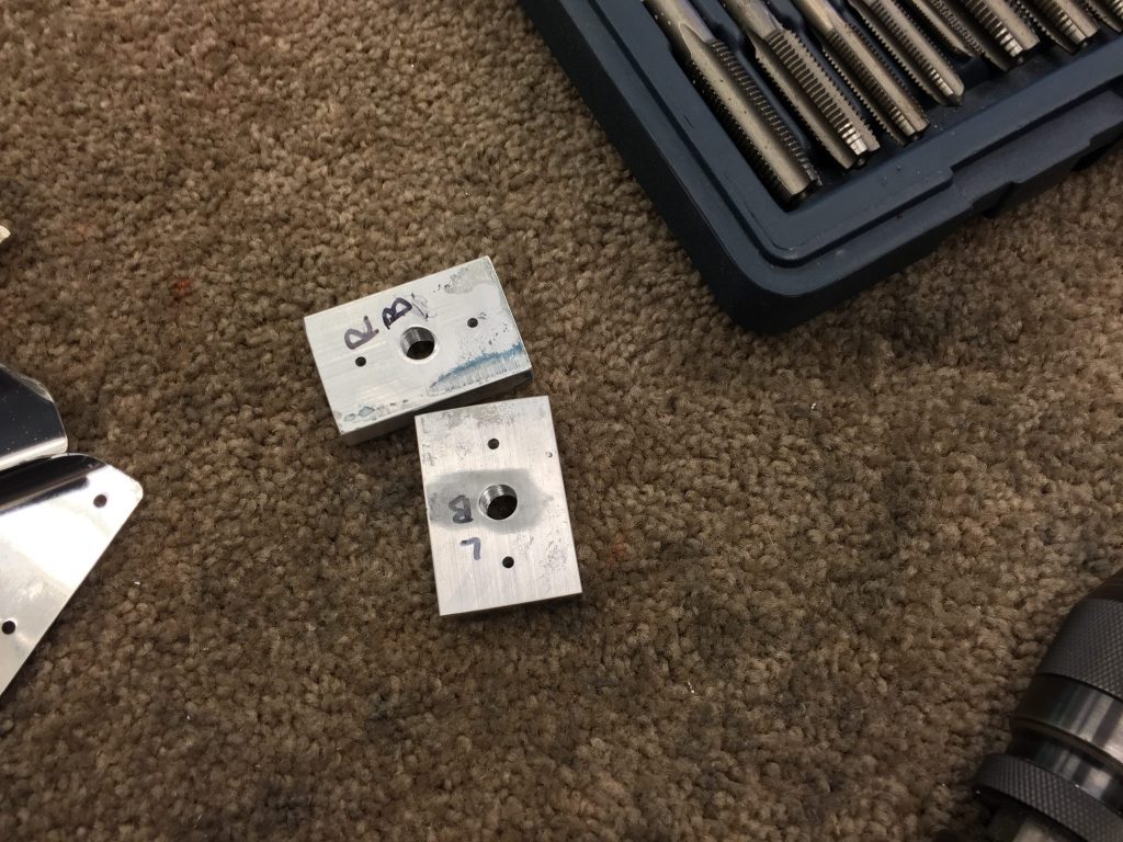
The tie down ring gusset was next. This gusset if structural support behind the passengers backrest bulkhead and the upper longeron. You also have the option of putting in a tie down ring storage in this spot. This is for the Van’s tie down rings that are meant to be removed before flight and stored here. If you can remember I went with smaller aftermarket ones that can stay in all the time. I still went ahead with the plans just in case I ever wanted the bigger rings I would have this done now. I bought som 3/8″ thick bar stock from McMaster Carr and cut and drilled per the dimensions. I then grabbed my tap set and tapped for 3/8″-16 threads needed.
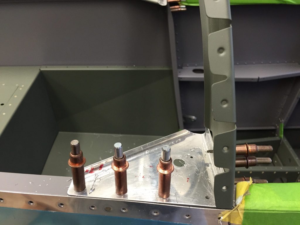
Before riveting those in-place I put them on the bulkhead and matched drilled the longeron’s.
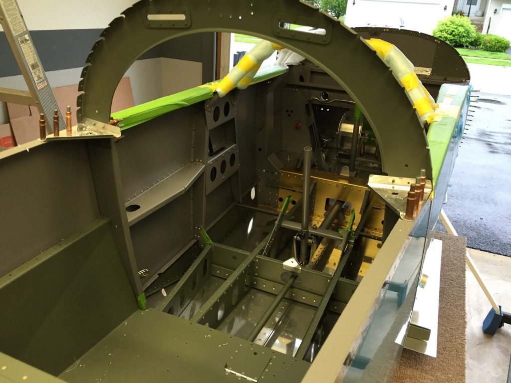
A couple days later I was finished with priming, painting and riveting all these parts.
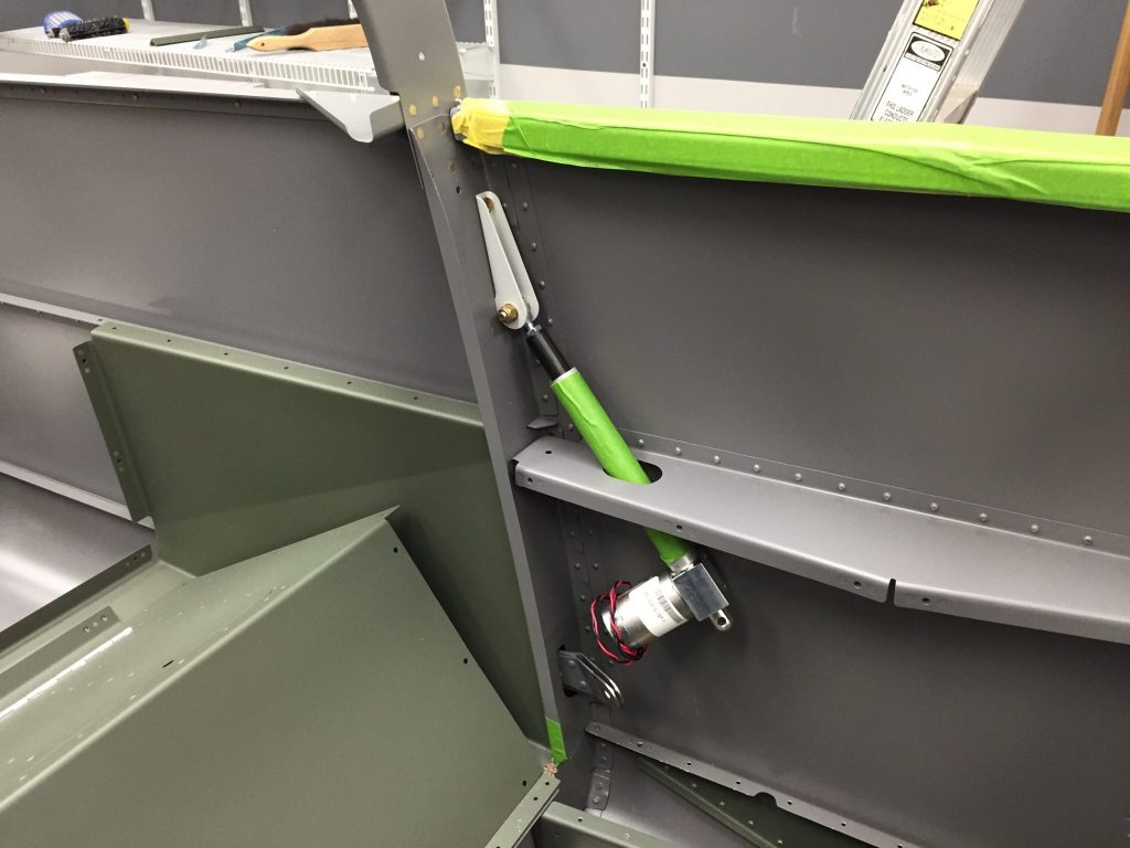
Next I installed the upper flap moter bracket and installed the flap moter. I didn’t instal the lower end as the floors are not in yet.
From there I wanted to see if I needed to trim the bottom of the VS at the forward end. Some builders, including Glen, had to trim this a little as the skin was in contact with it. I guess I was lucky as mine was just fine. When I called T to come look at the progress she made me get in a shot. 😀
As with this entire build I got to take all the parts off including the VS so I could work the up and down travel of the elevators. There are two travel stops, one for the up and one for the down. These limit the travel of the elevator horns and can be adjusted. The forward movement or down elevator has a limit of between 20°-25°. As mine stood with no change I was at 23°. Due to the horns not being matched only the left one hit the stop when you really want both. After discussing this with my buddy I decided it’s not a big deal as it would be very rare if at all that you would got that stop in flight. So I left it as is and worked on the aft or up stop. This one could be hit inflight especially in acrobatics so I would work at it to get both hitting. The final product was to trim the right side of the stop to almost flush and the left about 1/4″ remaining. I angled both sides so that most of the flange of the horns came in contact. I achieved 26.8° with the range between 25° and 30°. I’m happy with this result.
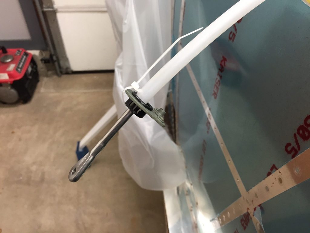
Last night I decided to do a little work which consisted of installing the rudder cables. There are two protective sleeves one for the aft exit hole and one for the section that lies next to the passenger foot wells. You start from the aft end and feed the cable through snap bushings and holes in all the bullheads. Before going through the center section you need to secure the end of the protective sleeve to the floor support snap bushing. You drill a small hole in the sleeve and zip tie it to the bushing and bracket.
After feeding it through all the holes I went back to secure the aft end with an Adell clamp.
Here is a view of the cables running the length of the fuselage.
Some of you may notice an error in the last photo…yep I installed the forward sleeve aft of the secure point! It should be forward of that point and go into the yellow center section there by protecting the cable for the foot well. Not a big deal and I just cut the zip tie’s and slid them forward, put a new hole in that end and re zip tied them.
So that’s my multi day post. These next 5 weeks will be spuradic as I close on my home in 3 weeks and close on our new home in 5 weeks. That means reduced a Hangar time and a couple of weeks of no hangar time when we are homeless! I’ll try my best to keep you updated.
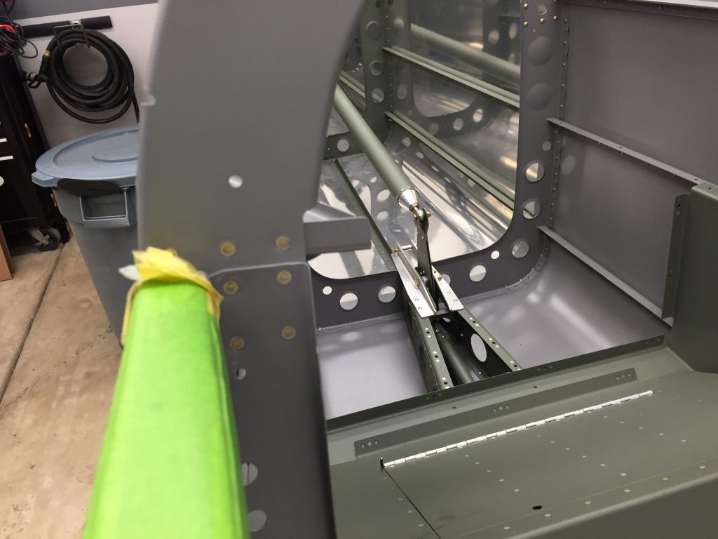
I got to work on the flight controls this afternoon with adjusting the rod ends that hang downward to connect the control structure. These have measurements from the support to the center of the rod end which is a little difficult to see without a mirror. I installed the pilot and passenger control sticks into the control structure. From there I connected the control tube that links the pilot and passenger control sticks. I will say getting the bolt and various washers in place is a real pain. I can’t imagine doing this without the washer wrenches. Once those are tied together I connected the control tube that connects the sticks to the bell crank. The plans have you do this first before bolting the bell crank in place but it doesn’t tell you to slide the bell crank into the area it will sit as there isn’t enough room to slide it into place. So I took it apart, pain in the butt, and slide the bell crank into the opening and reconnected the tube. Now I could bolt the bell crank into position, which is not very easy as well.I texted my buddy Glen to say I’m glad I didn’t have to remove the bell crank because it was a pain in the butt. He replied by don’t forget the bolt that holds the autopilot servo! Oops that’s exactly what I did! So I had to undo the bell crank, remove the bell crank, drill the hole for the autopilot servo arm and put the bolt in place for the servo. This bolt lines up inside the bell crank bracket and would be a real pain to put in down the road.
From there I added the aft control tube and connected it to the bell crank. In clamped the elevators in trail so that they were in the neutra position. Before I connected the control tube to the elevator horns I verified that the control sticks were equal to each other. I found that they were a little off based on my digital level. So I undid the rod end on the pilots control stick and adjusted it to get both sticks perfect. Now I connected the aft end of the aft control tube to the horns that were still in the neutra position. The control sticks should now be at 90° compared to the fuselage which I readjusted to level. They were off at 89.7° so I adjusted the aft end a turn and got them spot on.
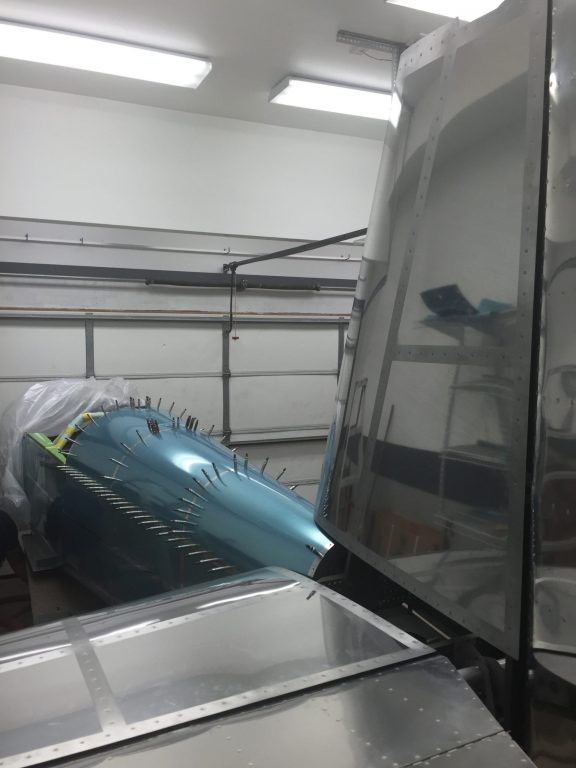
I released the clamps to see my controls and elevators moving in unison which was pretty cool. I did notice that there was a little binding in the middle part of the throw. After some inspection I found that the bolt I put in place in the bell crank for the autopilot servo was rubbing on the rivet heads a little. I have my buddy Glen confirming that I have the washers in the correct spot for that bolt. If I have that wrong I’m going to have to take the bell crank off again for the third time! But I’m getting better at it! After running some errands I got a call from Glen looking at his bell crank and confirmed that he only had one washer underneath the bolt instead of two. The plans called for one washer and a star washer to help keep the bolt from backing out. After a short discussion I decided to remove the bolt and remove both washers and replaced with one thin washer. The thought is that the bolt head is drilled and I will eventually safety wire it after installation of the servo. So off came the bell crank one more time, I’m getting pretty good at installing it! I decided that was a good time to clean up shop as I would be gone for a couple days on a trip. What better place to protect the parts then when they are in their correct position. I needed to store the VS and writer so I put both on the fuselage.
While I was cleaning up parking I grabbed the tail wheel assembly and put it into position. You can see the Bell tailwheel fork that I bought to replace the stock Van’s one.
I got started today by retrieving the elevators from my storage so that I could install them and drill the horns. Before startinging I removed the VS so I could clean, debur, scuff and prime the forward spar attach bracket and spacer. When that was done I grabbed the left elevator and put it in place with my temporary pins. I needed to trim the elevator skins where they met the counterweights of the elevator. I marked them and cut the skins and filed it down to a good edge. I repeated the process on the right side.
Next I needed to trim the lower flange of the rear spar on the HS to allow for clearance on the elevator horns.
I marked the flange with a sharpie and then removed both elevators and the HS from the fuselage. I also removed the hinge so that it was not damaged during the cut. I needed to be real careful when I cut this so that I did not damage the spar support bar underneath. I grabbed a scrap piece of .025 and drilled a hole so that I could Cleco it into position to protect the bar.
The cat went pretty easy with no damage, I cleaned up the corners, touched up the primer and reinstalled the hinge.
I put the HS back into position and rebolted it down. Next up was the process of drilling the bolt hole through both horns of the left and right elevator for the center hinge bearing. This bolt is a 1/4″ AN4 but I would start with a #40 hole. To get the whole centered I used a drill bushing that I bought from McMaster-Carr that had an O.D. of 1/4″ and a #40 I.D. I did have to sand down the outside edge just a little to get it to fit inside the bearing. I did this by chucking the bushing in my drillpress and using sandpaper as it turned.
I reinstalled the left elevator only so that I could drill its horn. The process is fairly simple, you just need to put the elevator in line with the HS by clamping the counterweight so that it is even with the HS.
Once it’s in place in aligned I slid the bushing back in the bearing and slid it tight up against the elevator horn. I grabbed my 12″ #40 drillbit and drill the hole in the horn.
I removed the elevator and enlarged the hole with a #19 drillbit followed by my 1/4″ reamer.
I repeated the process on the right side.
I grabbed the AN4 bolt, nut and a few washers to attach the elevator horns. There is a gap between the horn and the bearing and it varies due to the welding. You just use a combination of washers to fill the gap. I ended up with 3 washers on the left and 2 and 1 thin on the right.
Putting these washers was made easy with my washer wrench set I bought last year.
With the bolt tightened down I was able to move the elevators together which was pretty cool.
A very common thing is to have the elevator horns be off a little as the welding process can vary from lot to lot. Mine was no different from other builders
The bottom of the horns is where the elevator controls connect via a rod end. The measurement is 3/8″ up and 3/8″ back to give good edge distance. You just choose the aft most horn for these measurements. That way the edge distance on the other horn is even better. In my case the right horn was the aft most one. I marked the whole and drilled a #40 hole and followed that with my 3/16″ reamer. Since there is a gap between the two horns the plans how do you make a wood drill spacer to help align the drillbit for the other horn. I grabbed a piece of oak and sanded it down to just fit between the two horns which was approximately 7/8″. I drilled a #12 hole in the wood block and slid it into place with a clamp.
I used that would block to drill the left horn to match the holes. Now they are ready to connect to the elevator controls. Before that can happen I needed to put the center control tube in place. This tube will rotate left and right to control the ailerons and will house a control are in the center for a forward and aft movement to control the elevators. It was a little tough getting it into place through the center section rectangular hole. Once it was through I added the rod ends to it and temporarily bolted them in the supports.
It was getting late so that’s where I decided to call it a night.l after another great day in the hangar.
 After all the edge work I clecko’ed the parts together, as you can see the center panel is offset down one hole, this allows the parts to be inserted into the fuselage and still give you access to the clecko’s. This panel will eventually be held into position with screws allowing you to remove it to work on your flight instruments.
 I needed to countersink all the holes in the two side panels so that the instrument panel will lay flat.
  I then clecko’ed the parts together and put them in their place.
  Since I needed to put the windscreen roll bar in next and it’s not painted yet I moved ahead to the forward top skin and started working on those parts. There are two filler strips that make a lip for the forward baggage door to lay on when closed. I cleaned their edges and deburred them.
  The top skin has two parts that need to be cut out, the first is the baggage door area and the second is the cut out for the glare shield above the instruments. I used my dremel to cut these out and clean the edges up.
 I then cleaned up all the edges on the top skin and then clecko’ed the filler strips to the underside with just a couple of clecko’s. Then the skin got layer on top of the fuselage to start clecko’ing it in place.


 From this point I decided to clean up shop and grab the stuff I needed to paint the roll bar at home in the garage. I will get it painted tonight and have it ready for the next couple of days. A good day in the hangar!