Wing Tip Lens

Time: 4 Hours

Now that I had the landing/taxi, NAV and strobe lights installed I broke out the lens that cover this area. Vans sends these as on piece that needs to separated for the left and right side. The material feels flexible and not like plastic so I did some tests using snips to cut based on other builders experience. They worked perfect and I separated the two halfs easily. They are way to big and need to be cut down to fit your opening. I started with the right wingtip and positioned the lens over the opening until I had a good shape and the curve matched the wingtip. I taped in place and use masking tape to mark the edge of the cutout. 

Are use the snips to cut along this line for the bottom cut.  With that edge nested after being cut I then worked on the other edge. 

After I had both edges cut are used sandpaper to fine-tune and get the lens to nest all the way around the opening. Once I was happy with that I drilled two holes to hold them in place as I continue to work the shape.

I cleaned up the edges so they sat within the lip all the way around. I was pretty happy with most of the fit except a few areas that had a very slight gap under the lens where it didn’t sit flat on the wingtip. What I decided would be the easiest fix for this was to sand all the fiberglass on the lip, wax the inside of the lens, apply a thin layer of epoxy/fairing filler to the tip and put the lens back in place. I applied tape to the edge to edge and buttered the lip with the epoxy and put the lens in place. 

This should match the inside edge of the lens to the fiberglass and make a solid fit.  I let them cure overnight and started the process of removing the lenses. I used a pop sickle stick to slide under the lens and work my around the lens. The left side released without any issues and looked great however when I worked the right side it was a different story. When I got to the lower side I heard a pop and noticed that the lens cracked at the drilled hole followed by another right next to it, that lens was finished. So rather than fretting this I just jumped on the laptop and ordered another set of lenses from Vans. I then sanded all the edges of the wingtip to remove the epoxy I just put on so I can start over with the new ones. I’m thinking this time I’ll live with the little amount of play I have rather than risk cracking another lens. I takes Vans about a week to ship things to my house so I decided to do some serious shop space cleaning and removed a lot of stock/supplies that I just no longer need. It’s amazing how much dust is created with composite materials! It took 8 days for the lens to come so I’ll be back at it soon. I also ordered a axle nut wrench that Vans cuts and you rivet together. I will keep this in my aircraft tool bag so I can change a tire on the road. 

It’s Easter break with my kids this week and taking a much needed break the following week to join my girl in Kona, HI after her weeklong program is over at the end of this week. It’s been kinda nice having only a few little tasks left to do on the RV which forces me to enjoy other things around me! I’ll be back to being supper busy building after I order and receive my engine from AeroSport power. The goal is to order it around the end of June and attend their build school sometime September/October timeframe. 

Landing/Taxi Lights

Time: 8 Hours

This last summer at AirVenture I purchased my landing/taxi and position lights from AeroLed. My plan was as soon as I ran out of stuff to do this Winter I would work on these lights, that time has come! The wheel pants are almost done so I figured I would start the process of installing these lights. I would start with the landing/taxi lights first. These are specifically made for the RV aircraft and the shape of there fiberglass tips. The model is AeroSunVx and include led’s for taxi and led’s for landing. They send a wood template to use to mark the area to cut as well as the two adjustment screws. 

Once you have all the sight slots adjusted on the template you drill the two holes and clecko it in place. 

Then you can use the template to mark the area that needs to be cut.

I started with a Dremel cut off wheel followed by the Dremel drum sanding tool to get close to the line. 

Then I used 80 grit sandpaper by hand to take it right up to and removing most of the line. The plans have you put two layers of blue painters tape around the perimeter of the light to give protection as well as spacing. You then insert the light from inside the fiberglass tip to see the points that are tight. With a single layer of sand paper facing away from light you slide it between the light and fiberglass and pull outward. This sands the fiberglass to the shape of the light as you push pressure on the light. This is a very very slow process but they tell you to have patience with this so that the reveal is equal all the way around as the adjustment screws are in place. 

Once you have the light in perfect shape it’s time to mount the pivot arm to the leading edge. This arm just connect to a rubber bushing housed in a plactic piece that is the shape of the leading edge. The plactic piece gets permanently mounted and the bushing allows for the light to pivot and vibration control. You can drill holes and blind rivet it in place or epoxy it. I decided to go the later route so I didn’t have four blind rivet heads showing. I did drill two holes so that I could hold it in place as the epoxy cured. So I mixed up some epoxy/flox and covered the part and installed the light. 

While this was setting up I started work on the AeroLed Pulsar NS (Nav/Strobe). This was pretty easy to line up with the dimensions provided. They have a attach bracket that is held in place with three screws.  I decided to use nyloc nuts instead of nutplates. 

Then I drilled a 3/4″ hole for the wires to pass through. After feeding the wires through the hole you slide the light ontonthe bracket and slide it forward. There is a set screw at the aft end that holds it in place. 

I repeated the entire process on the opposite wingtip with the same results. 

After this cures I will remove the lights and clean up the edges and re-prime the tips as well as work on the lenses that cover the lights. I will also finish up the wiring and make a temporary pigtail so I can put the tips by the fuselage and test them without having to put the wings on. 

Pitot Staic Line

Time: 8 Hours

I needed to run the pitot(airspeed) and AOA(angle of attack) lines inside the fuselage and the left wing. I decided where I wanted to run the lines and drilled for two snap bushings at each bulkhead as they went aft from the fuselage side where they will make a 90° and exit to go into the left wing. Once I had the bushings in I ran the lines and secure them with zip ties as needed to keep them out of the way of things like the flap push rod. 


I also needed to reroute the two lines in the wing as I had originally followed the tooling holes in the ribs. The problem with this is it puts the lines exiting the wing too close to the wings spar. Glenn had already figured this out so I adjusted mine like his. I just change the location of the innermost rib snap bushings. In between the last two ribs I rerouted the lines to exit in a better location.  I used a #6 adel clamp to secure the lines to the rib. These lines will be cut to a perfect length once we reinstall the wings for the final time and slide thru the snap bushings in the fuselage side. They will attach to the two elbows that will be inside the fuselage. 

While I was working on the right wing and the pitot/AOA lines I decided to work on the wiring that I needed to run to the pitot and wing tip. On the right wing I will need a 3 wire harness to the tip for the land/taxi lights, a 3 wire(with shielding) harness to the tip for the NAV/Strobe and a 3 wire harness to the pitot tube for pitot heat. At the wing root I used plain Molex connectors as this area should be sealed up from moisture with the rubber seal that will tie the flashing to the fuselage side. Out in the wing tip I might get moisture thru the hinge that I have holding them on so I used Seal-All connectors form McMaster Carr to help prevent corrosion. With the NAV/Stobe I carried the shielding thru the wing root connector and left it un-terminated at the wingtip as per AeroLED’s recommendation.  I started with all the Molex connectors at the wing root and secured them with a adel clamp. 


When we go to attach the wings for the final time I left enough length on the fuselage side to be able to connect the wires with plenty of space as we slide the wings in place. Then as the wings slide into place the extra wire will be pulled into the fuselage and out of the way under the passengers foot wells. 
Once I had the wing root wires secured I moved to the outboard end to work on the weather proof ends. They work just like a Molex except the have a rubber seal that you put on the wire before crimping. Once the wire is crimped you crimp the seal to hold it in place. 

These seals fit nicely into the back of the connector and prevent moisture from getting in.

 Then there is a back peice that snaps into place to hold the wire and seal in place. 

I completed this process for both the land/taxi lights and the NAV/strobe lights and secured them with an adel clamps and zip tied the remaining parts in their bag to the harness so I don’t loose them for later. Then when I get my lights bought I will complete the mating end of the connector on the wires from the lights and make them long enough to connect them as I install the tips. 

I also ordered the Dunon ARINC module, the device that talks between the Skyview system and a certified GPS, so that I could drill and mount the nutplates to the bracket I made a while ago. I really didn’t need this part but I wanted to rivet the bracket to the fuselage and I needed the nutplates to be drilled first. 


So that’s where I stopped and called it a day. 

Fuel Tank Bracket

Time: 2 Hours

Once the wings are removed you have access to the fuel tank attach bracket that is part of the wing structure. If you remember I drilled this bracket while it was mated to the bracket that is part of the fuselage. Now that the hole has been drilled in the wing side bracket you need to extend the hole to a slot. The theory for this is in the event of an emergency landing or accident you want the wings to shear away from the fuselage as they absorb some of the energy that you have during an accident. The wings are meant to break away aft or towards the tail so you want the forward part of the wing to be easily separated in this event. This slot allows the bolt to support the inboard end of the fuel tank up and down but will shear away as the wings are bent back in an accident. So I started with a mark 1/4″ wide and cut the slot just inside of those lines. I then used a file to clean up the edges and open until a 1/4″ bolt would easily slide through the slot. Filing this thick bracket is what took the most time but I wanted to make sure I didn’t take too much. All in all I’m real happy with how they turned out. 

Wing/Fuselage Flashing

Time: 8 Hours

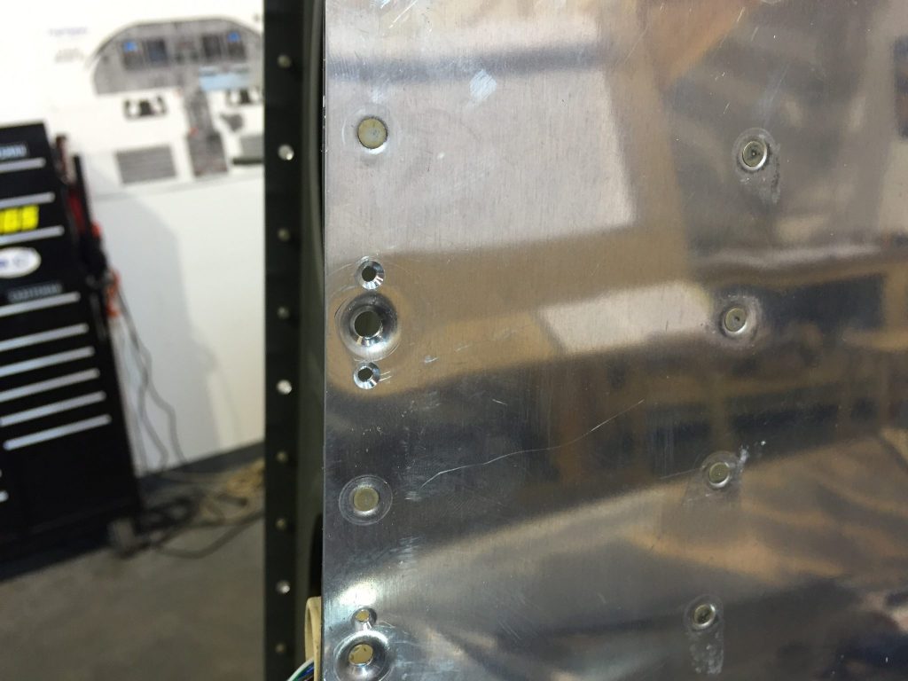
With the wings removed I can finish up the work on the holes drilled for the flashing that closes up the wing/fuselage gap. The holes were drilled with the wings in place but you don’t have enough access to finish the work that is required. All these holes will eventually have a acres in them to hold the flashing in place but allow easy removal for work. All of the holes will get a nutplate for a #8 screw. The flashing holes will be dimpled for flush screws so all the underlying skins on the wing will either be dimpled or countersunk depending on the area. The fuel tank edge can be dimpled as well as the bottom wing skin. The top has to be countersunk since it has three layers due to the extra wing walk material that beefs up the area to walk on. I started with the fuel tanks working on both wings. 

I used one winged nutplates for the two spots where the fuel tanks reach the wing spar. You could remove the fuel tank and have access to rivet a normal two winged nutplates. With the one winged nutplates I could rivet them without removing the tanks. Thanks again to Glenn for having his wings here so that I could eyeball them when I was scratching my head on how to rivet the normal ones. Once I had all the tank ones done I moved to the single nutplate that falls on the wing spar flange. I countersunk the rivet holes for the nutplate and grabbed my rivet gun and bucking bar and set those rivets. With the nutplate in position I countersunk the screw hole with a #30 bit. This bit head will fit inside the nutplate screw hole and keep it aligned. 


From here I worked my way up the bottom skins which just needed nutplate rivet holes drilled and dimpled as well as the #8 holes dimpled. 

All the holes on the top skin will be treated like the wing spar flange and had the nutplate riveted in place and the. The screw hole countersunk. 

With all these holes done I can put the wingtips back on and store the wings for later work, landing/taxi light wiring and install, and out of the way. 


During a break I ordered and ran to pick up a couple boxes of screws from McMaster Carr. I wanted to get some black 8-32 torx screws 1/2″ long for my instrument panel. I thought these would look cool vs the gold colored ones that I already had. 

I though these looked so cool I ordered a box of black 8-32 phillips flush screws for my armrests and side panels from MicroFasteners.com as they carry 100° head screws in black and stainless. 
 My girl and the kids got me a Aircraft Spruce gift card for Father’s Day so I used that yesterday and ordered the Dynon autopilot control head that sits next to the intercom on my panel. I wanted this now so that I could test my trim buttons on the grips as well as the trim motors like the one I just installed for the roll trim. That should be here by the weekend for me to install. Thanks T, Drake, Chandler, Ellie and Cody.