Garmin GTN-625xi

Time: 1 Hour

My new Garmin GTN-625xi arrived this week which is about two weeks earlier than Garmin said it would get here. I had already bought and installed the rack, backplate and wiring harness for this GPS several years ago while working on the panel and all my wiring. My original plane was to get the GTN-650 which includes the COM radio and VOR/ILS radio. I later decided that I would never need an ILS or VOR for my needs as RNAV approaches will suite all my missions. So the GTN-625 was a better choice as it has the same GPS but not the COM or VOR/ILS radios. The rack is the same for both units and the backplate is as well you just have less connectors. So when this is it arrived there really was t much to do except to slide it in the rack, tighten down the mounting mechanism and power it up. Well you also keep your fingers crossed that all the wiring you did several years ago was right! With the flick of the master battery and avionics switches the GTN popped to life. I had one small issue that revealed itself after power up…configuration module needs service.

I had no idea what that was so I went online to research it. Turns out there is this little device, looks like a very small motherboard, that has four wires/pins off of it that resides inside the back shell of the wiring harness connected to the backplate. so what does this module do…apparently it stores all your settings for the unit. That way if you remove the unit for service and it comes back in a factory setting mode you can restore all the settings. Well I didn’t know about this little device back when I installed the rack/backplate/wiring harness. Luckily for me I received a wiring harness/rack/backplate with the unit. I opened up the new backplate and removed the module and it’s four pins. I then opened up my harness and installed said module and pins. With the module in place and the harness reconnected I powered the GTN back up and boom the error was gone and all was right in the GPS world. It took about 15 minutes to configure both the GTN and the Dynon SkyView ARINC module to allow the two devices to talk to each other. I then put in a quick flight plan from our home C77 to Omaha OMA to see if it was depicted on the SkyView. There it was and the autopilot would fly it perfectly. I put in an approach, RNAV 14L, at OMA and it displayed all the points including the holding pattern. That was just a quick test to make sure it displayed correctly on the map. I have a lot to learn on how to properly operate this unit. What this GTN allows me to do is utilize the air traffic system under instrument flight rules, IFR, since this unit is certified by the FAA and enhances the missions I can fly tremendously.

A nice thing about Garmin is they have an iPad app that allows you to virtually do everything the real unit can do. That allows you to practice and work along side a Garmin instructor led online class.

Bose A20’s with Bluetooth

Time: 0 Hours

So when I came to United Airlines two years ago I needed a new headset, one that would work in the 737 environment. That meant one that could work on an intercom and one that would be easy to use if the captain didn’t wear a headset (yes there are still pilots who use the single ear piece boom mic). My go to headset was the Bose ProFlights. They work awesome, are lightweight and fit the bill for headset or partial headset so you can hear the pilot if they are not wearing one. I highly recommend them if you are in a jet environment. I only have one complaint if you could call it that…the original cable from the headset to the controller and to the jacks was pretty thick. Bose must have heard this and came out with the PF2’s with a much thinner cable. I have those now and love them.

So when it came time to pick a pair of headsets for the RV-8 I really didn’t need to look far as I knew the Bose A20’s were what we wanted. We had tried them on up at AirVenture 2019 and both Tricia and I loved the fit and quality. The sound is incredible as well which is what Bose is known for.

The new A20’s have Bluetooth built in which allows you to connect to several devices like and iPhone for music or the Garmin VIRB Ultra 30 camera so that when you record video of your flight it will also capture the intercom audio.

I placed the order and the two headsets arrived yesterday. So I decided to do a post of the unboxing.

I put the two AA batteries in and powered them up. The Active Noise Reduction (ANR) is awesome just like the ProFlights. I hit the Bluetooth button and was able to connect to my iPhone quickly. I played a little music and the sound was fantastic. The headsets have a selection so that when air traffic control transmits it mutes the music instantly so you can hear what they are saying.

I can’t wait to use these in the RV! They are going to definitely help reduce fatigue from the external noise that piston engine aircraft are known for.

Thanks Bose for producing an AWESOME product!

Extra USB Outlet

Time: 4 Hours

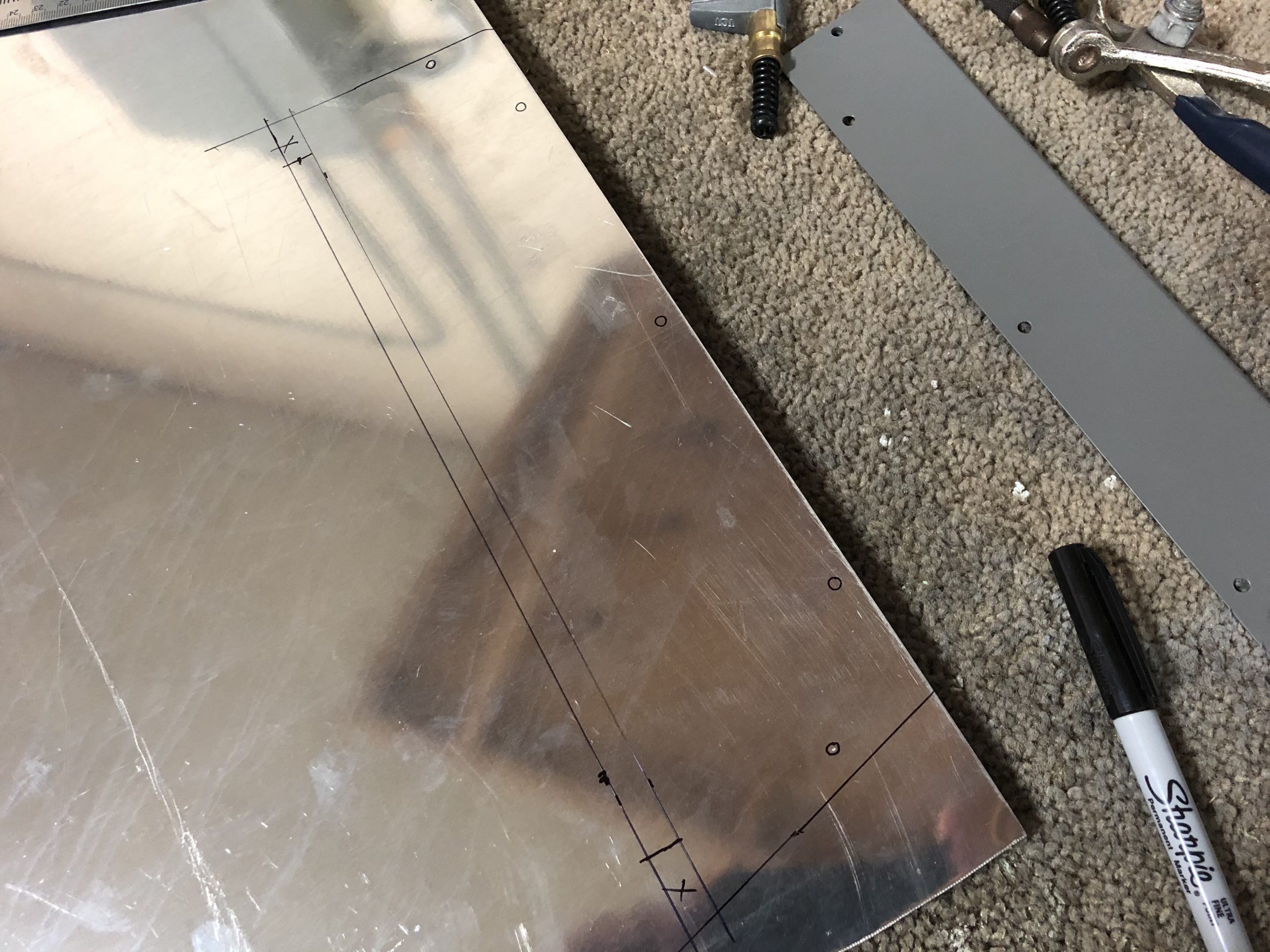
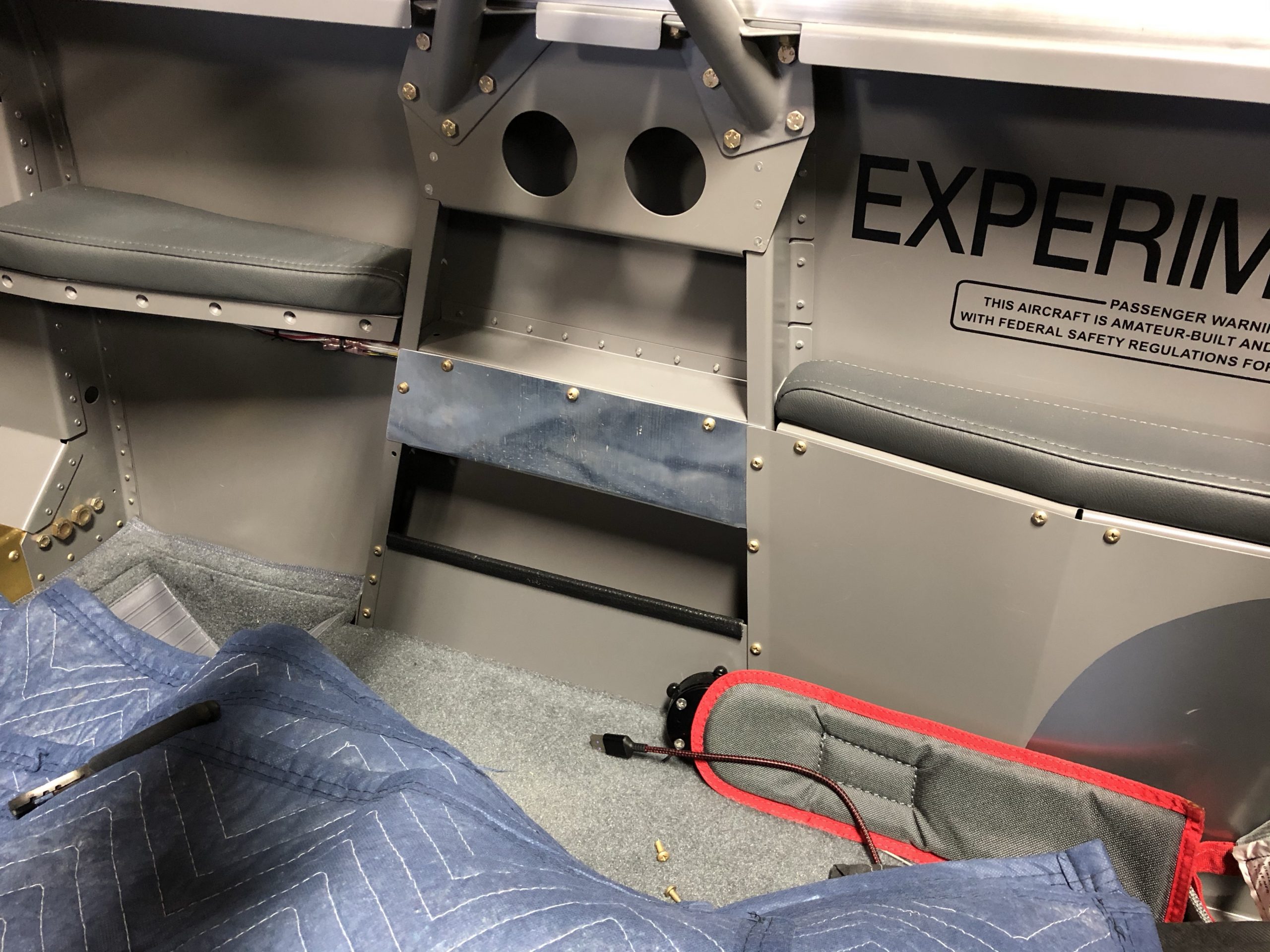
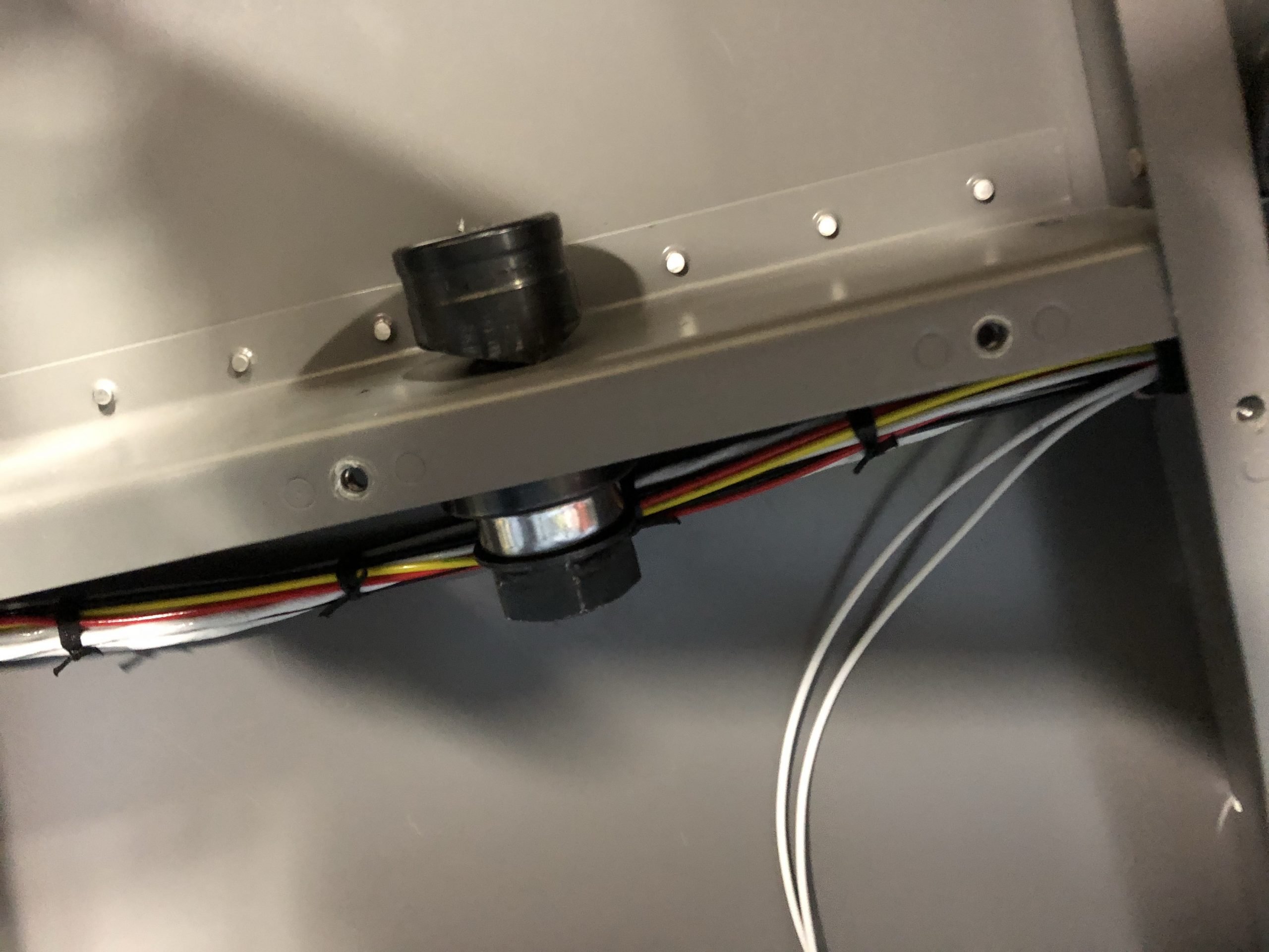
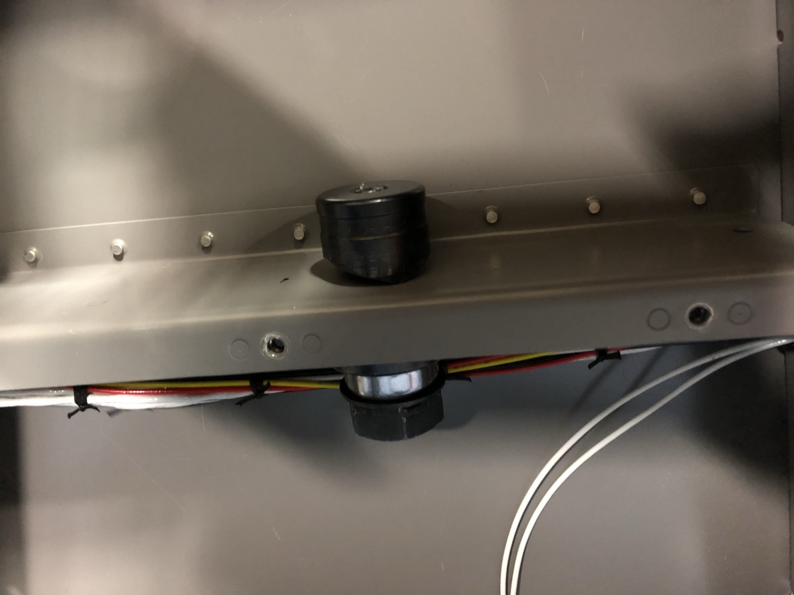
I decided that I wanted to have additional USB ports for charging the iPad and Garmin VIRB camera that I’m going to mount on the roll bar. Since we will usually enter the RV from the left side I will mount the camera on the right side. So the perfect place for the USB’s would be just below the roll bar on the right side. I decided to mount the outlet vertically so the USB’s would be facing up towards the iPad/camera. The horizontal support would work perfectly. I need to conceal the outlet as well as it’s wiring, so fabricating a side wall was the first task to complete. I took some measurements and drew a pattern on some sheet stock I had. I marked for the screw holes and a flange I would bend in the bottom to give the panel strength.

I cut the piece out on did the final shaping and smoothing with the files and 3M wheel. I then used the brake to bend the flange for rigidity. With all the screw holes drills and deburred I put it in place for a trial fit…perfect fit.

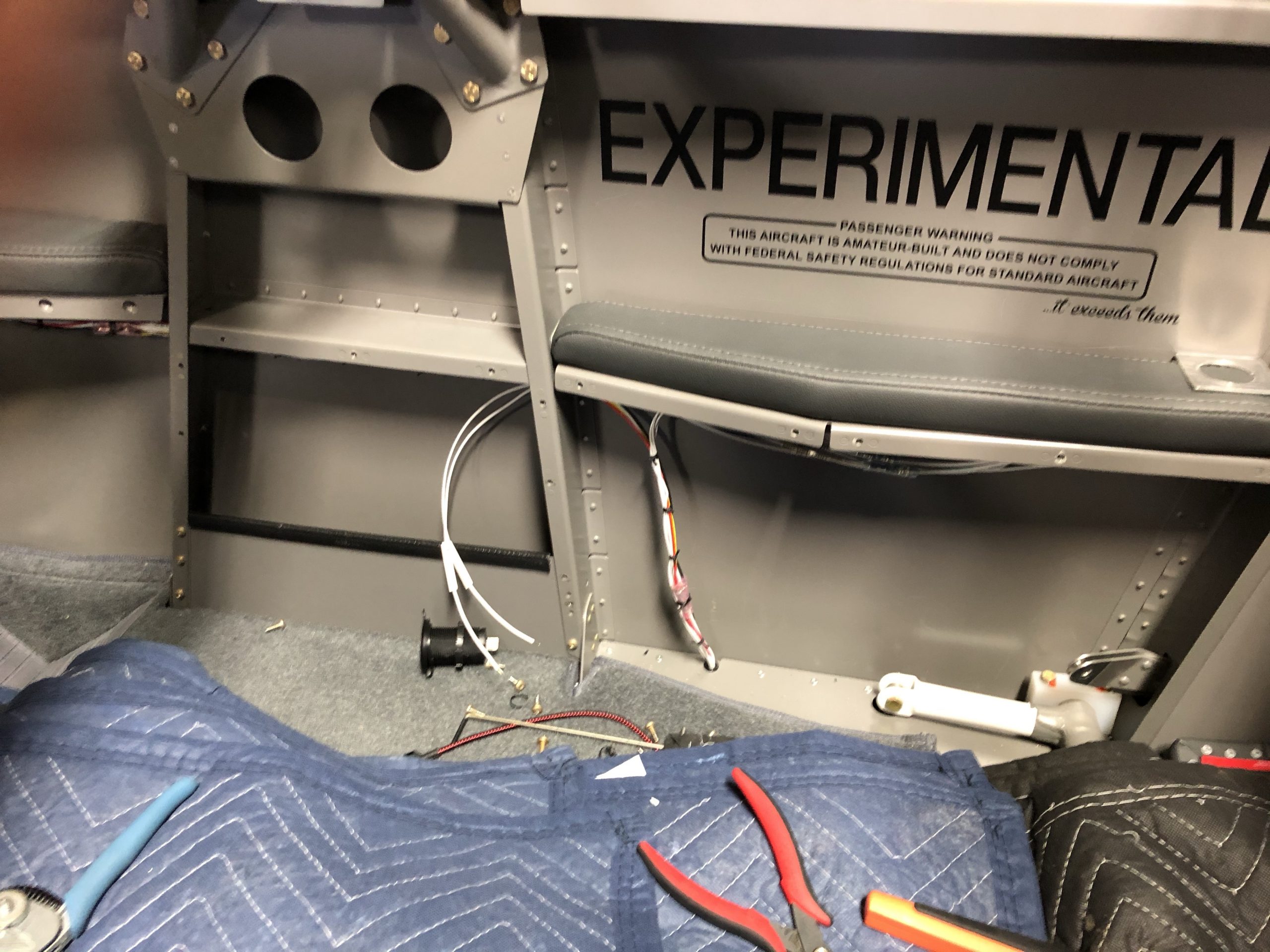
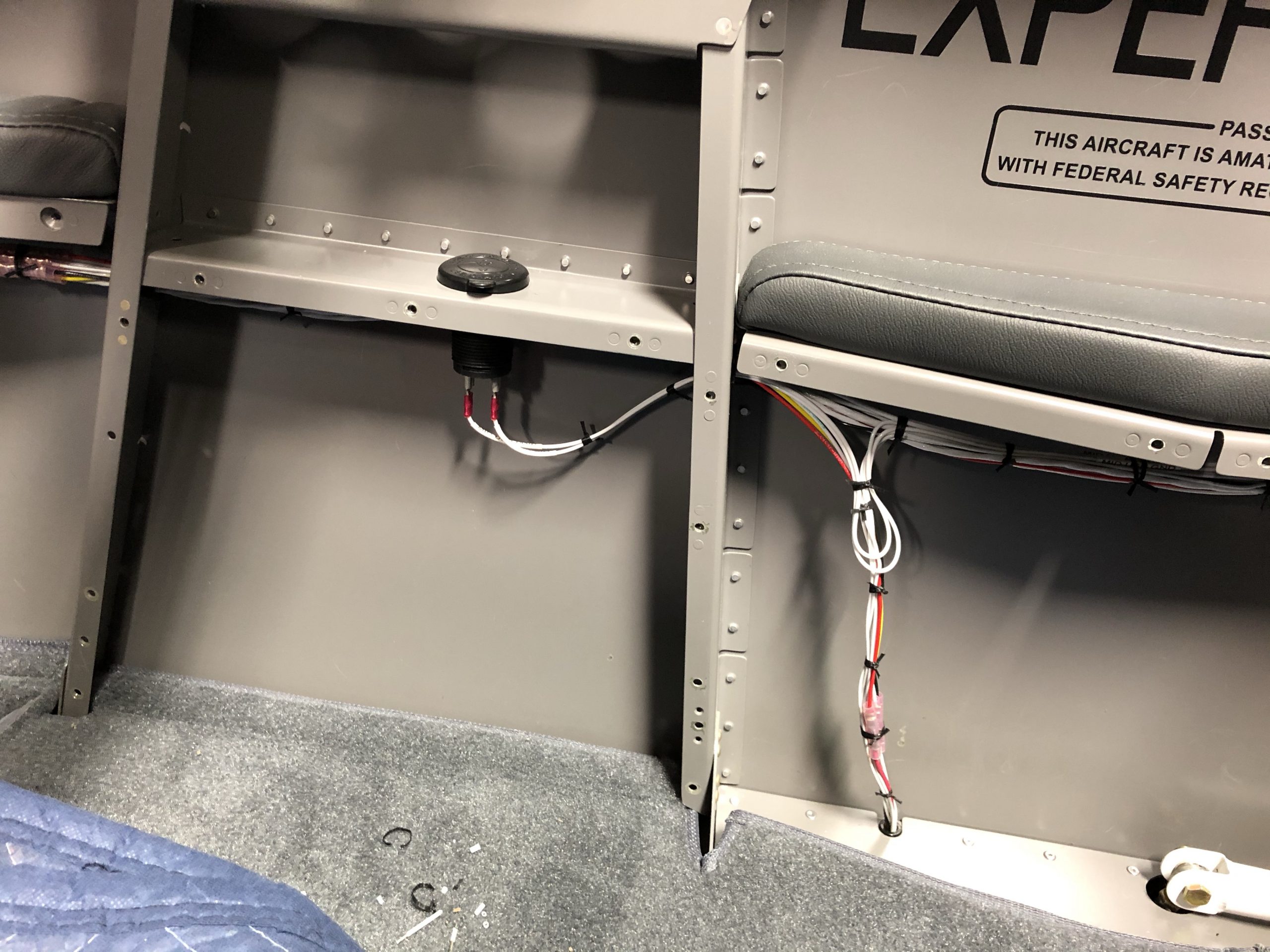
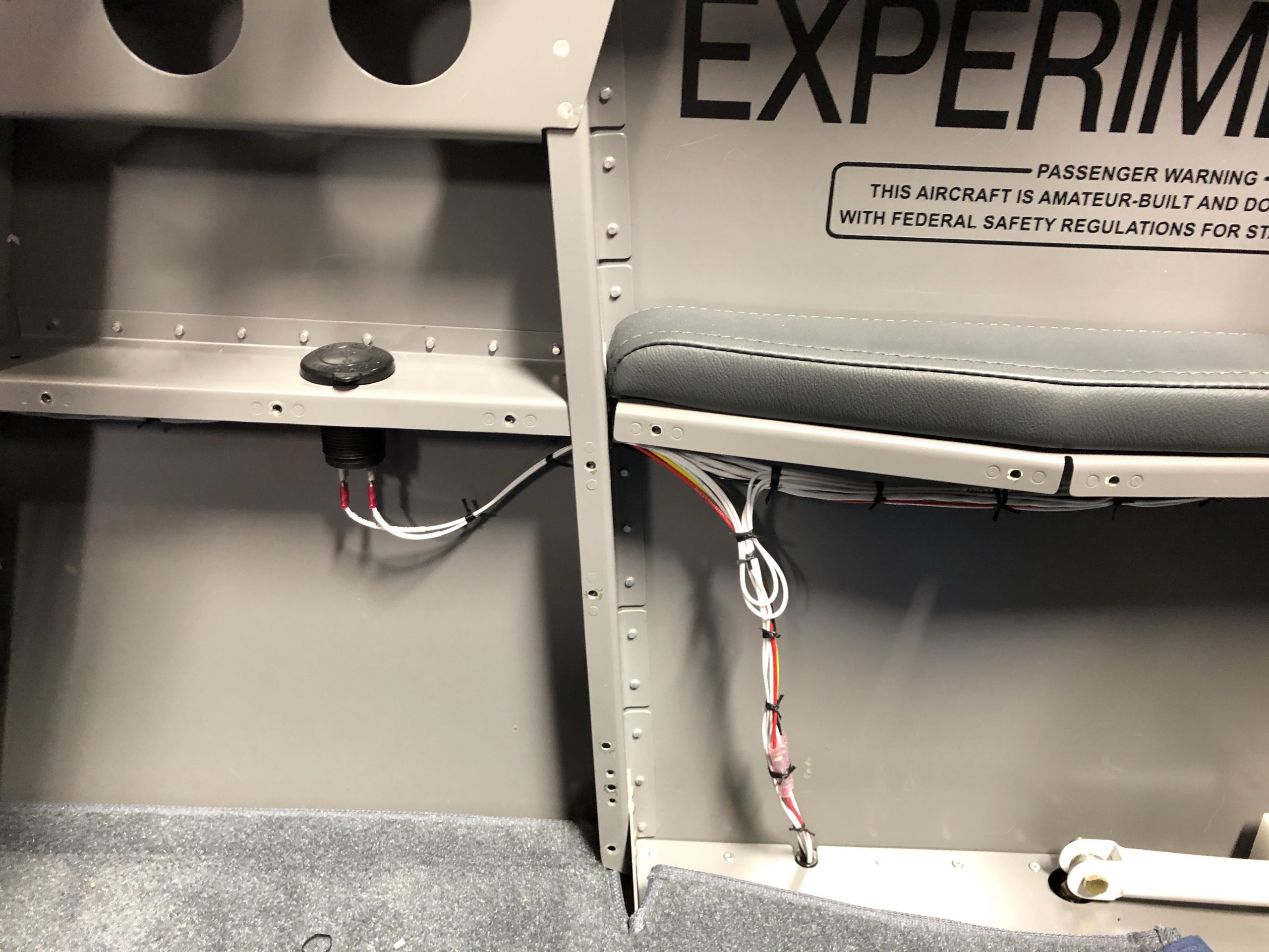
I original put the 12v outlet that was in the bulkhead just behind the passengers right elbow on one circuit that would allow for up to 10 amps. For the USB outlet that I’m going to replace there the total amps would be 4.8. So I could tap into that power source to provide for that new outlet. I removed the passenger right side panel to expose the wire bundle and located the two wires, ground and power, for the aft outlet, I will call the new outlet then mid outlet. I cut the two wires and labeled them with my shrink tube label machine. I crimped a butt splice onto the wires that lead to the aft outlet. The other ends of the wires I put into the splice but also added another 18awg wire to each for the new mid outlet and labeled them as such. I ran those new wires through the bulkhead and into the space just under where the new outlet will be. I re-laced all the wires back together and cleaned the harness back up.

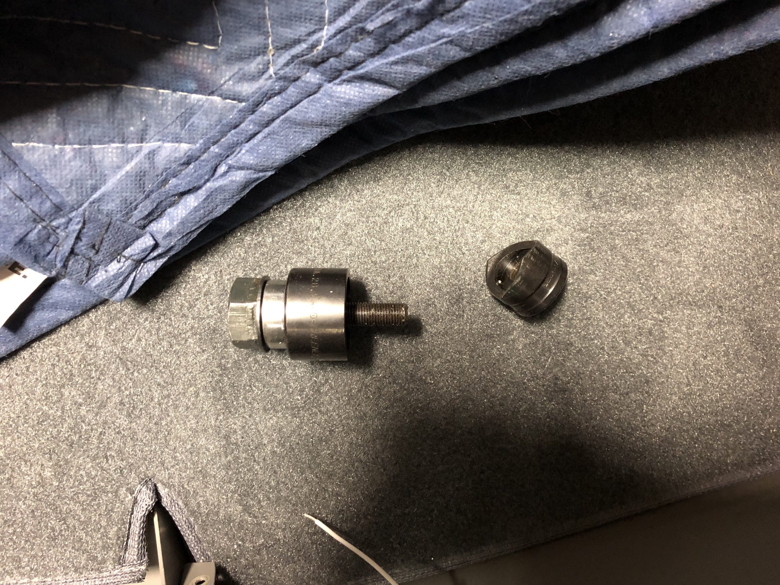
Now that the wires were all crimped and run to the new location I could work on putting the outlet into the support arm. There are a couple of rivets that I used to plug some homes and the nutplates in the flange(I put those in a long time ago for side panel that I didn’t use) all of which I needed to work around when deciding the spot for the outlet. Once I determined the spot I drilled a #30 hole followed by 3/8” hole using my step drill bit. Then I used my 1-1/8” hike punch to create the final hole.

The punch makes a perfect and clean hole that only requires a little edge cleaning compared to drilling. I then put the outlet in place and secured the nut to hold it tight. I labeled and crimped on the 1/4” tabs to attach the wires to the outlet. Once connected I pushed the extra wire back into the side panel area and laced them up.

A quick power up of the RV’s electrical system and the outlet worked perfectly. I spent the next hour cleaning up all the tools and replacing the side seatbelt and panel back in place. I primed and painted two coats on the new side panel and will install it when it’s dry and durable. So now I will have two USB ports by the instrument panel on the right armrest, two at the passengers right elbow and three(two in the outlet and the original single one in the bulkhead) for the mid area. We should have plenty of charging capabilities and able to keep everything powered up without cables all over.

Dynon SkyView 7”

Time: 1 Hour

My second SkyView screen arrived from Dynon directly. The process to install was simple as I had all the wiring harnesses done a couple years ago. So I just needed to plug in the three cables and screw it into the panel. I powered it up and went through all the steps to get it synced with the other screen as well as all the other devices.

I’m not sure how I will set up the screens and their layouts. I want to fly a little see what I like best. That’s the nice thing about Dynon SkyView is that you can setup and customize the screens to your liking. Here is a setup that I started with…the PFD(Primary Flight Display) at 80% on the 10” screen, the EMS(Engine Monitoring System) at 20% on the 10” screen and the Map screen at 100% on the 7” screen. Now all that’s left is the Garmin GTN 625xi GPS and my avionics are done.

Fuel Tank Calibration

Time: 2 Hours

I needed to calibrate the fuel capacitance plates in the fuel tanks. These aluminum plates measure electrical resistance through them. As fuel is added the resistance increases and the Dynon system and convert that to gallons after calibration. The process is pretty simple and the Dynon screen wakes you through it. You start with empty tanks and select start on the screen which takes a snapshot on the exact resistance in millivolts that it is seeing. Then you add two gallons of fuel and push the “add” button. The system takes a look at the resistance and locks it in. You then add two more gallons and repeat the process. You do this until you fill the tank completely. Now the system has 12 snap shots from empty to 21 gallons and their associated resistance. It then can make a curve connecting the dots to give you a very accurate reading of the fuel in the tanks. I didn’t take any photos of this process…that would’ve been boring.